Slider for slide fastener provided with automatic locking device

a technology of sliding mechanism and locking device, which is applied in the direction of slide mechanism, snap mechanism, press-button mechanism, etc., can solve the problems of difficult manufacture and high cost, and achieve the effect of preventing excessive spring deformation, ensuring stability, and smoothing of snapping for

Active Publication Date: 2006-04-13
YKK CORP
View PDF3 Cites 16 Cited by
  • Summary
  • Abstract
  • Description
  • Claims
  • Application Information

AI Technical Summary

Benefits of technology

[0007] The present invention has been made taking the foregoing problems into consideration and a main object of a first aspect in the present invention is to provide a slider for a slide fastener provided with an automatic locking device, wherein the slider comprises a body, a pull, and a spring with a locking pawl, and the spring with the locking pawl is made of a linear material that can be easily processed and attached on the body, and the locking pawl provided at a front end of the spring with the locking pawl is regulated so as to project by a predetermined amount to an element guide groove. And the slider with a high-quality automatic locking device can be economically and simply manufactured.
[0008] An object of a second aspect of the invention, in addition to the object of the first aspect, is to provide a slider for a slide fastener provided with an automatic locking device, wherein the spring with the locking pawl can be made of a long linear material having an approximately same cross section in its length direction and the spring with the locking pawl can be economically and simply manufactured.

Problems solved by technology

Therefore, it is difficult to easily manufacture the spring 105 and 205 with the locking pawl, dust due to punching out is generated, and a cost tends to be high because the material is used wastefully.

Method used


Image

  • Slider for slide fastener provided with automatic locking device
  • Slider for slide fastener provided with automatic locking device
  • Slider for slide fastener provided with automatic locking device

Examples


first embodiment

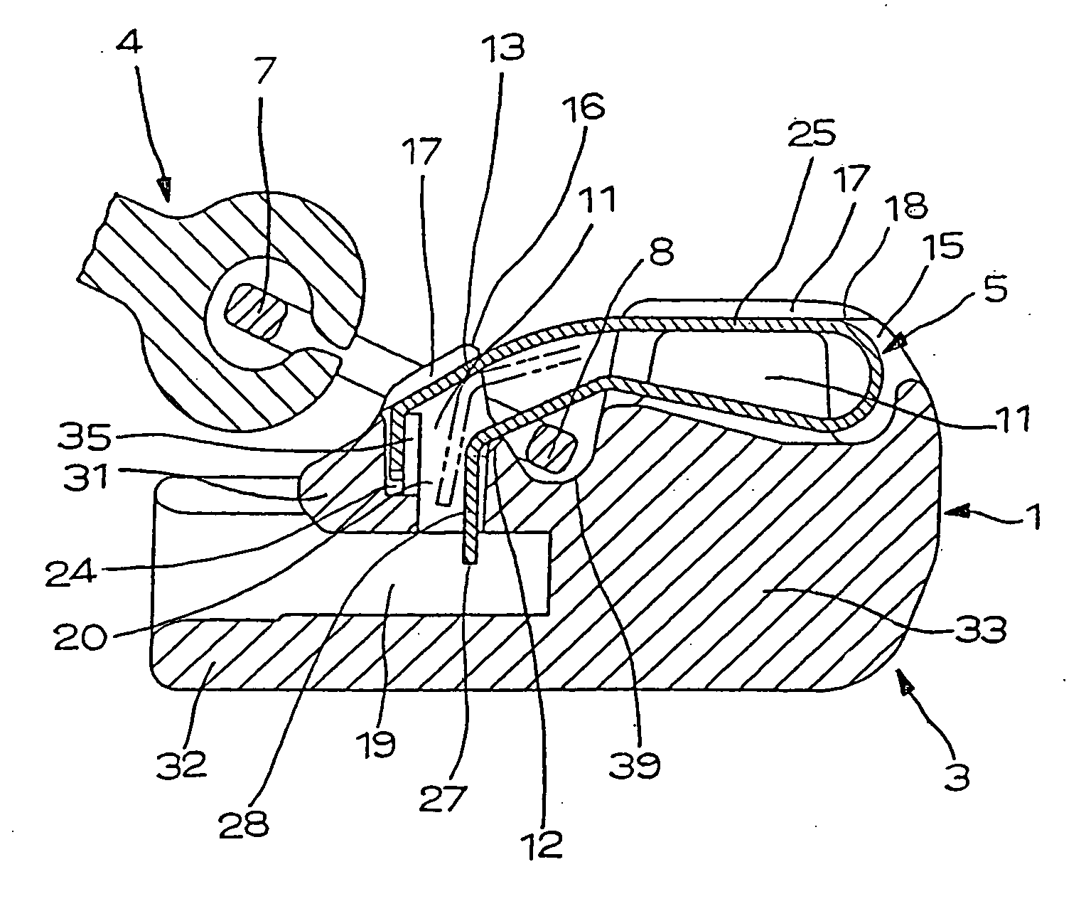
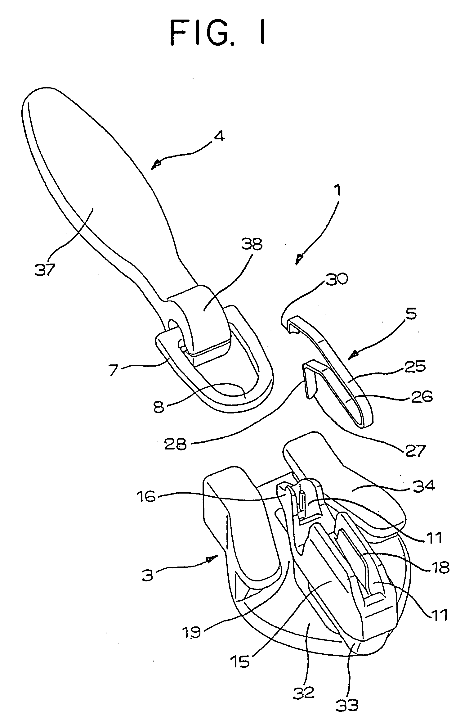
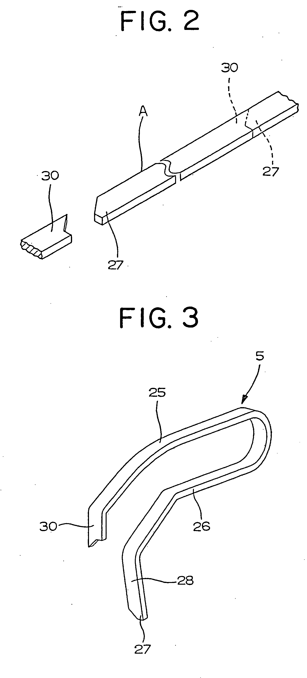
[0060] The slider for the slide fastener provided with the automatic locking device according to a first embodiment of the invention shown in FIGS. 1 to 9 is the hidden type of the slider 1. In this slider 1, the guide post 33 is built at the front end of the lower wing plate 32 on the body 3, the upper wing plate 31, of which a width becomes gradually narrow from a center of an upper face of this guide post 33 toward a rear side thereof, is extended, and a flange 34 of an inverted L-shape made of a vertical portion vertically rising from the lower wing plate 32 and a horizontal portion extended from a front end of the vertical portion in parallel with the lower wing plate 32 is built on both sides of the lower wing plate 32 to provide an element guide groove 19 for guiding a fastener element between the flange 34 and the guide post 33. The front side attaching portion 15 as the attaching portion 10 for attaching the spring 5 with the locking pawl is built at the upper side of the g...

second embodiment

[0069] The slide fastener provided with the automatic locking device according to a second embodiment of the invention shown in FIG. 10 is the slider 1 of the hidden type. On the body 3, the front side attaching portion 15 and the rear side attaching portion 16 are built, the front side attaching portion 15 is provided with the housing groove 11 likewise the above-described first embodiment, a bottom portion of the housing groove 11 is recessed in a curved manner, and the side wall 17 on each side is provided with the shelf portions 18 projecting toward the inside of the housing groove 11. An appearance of the rear side attaching portion 16 is equal with a former example, however, a wall face of a rear side of the pawl hole 20 is formed as a vertical face, the projection amount regulating portion 12 is formed by projecting and raising a front wall of the pawl hole 20 to an upper side, and further, as shown in FIG. 11, by bending the upper end portions of the side walls 17 on both si...

third embodiment

[0071] The slide fastener provided with the automatic locking device according to a third embodiment of the invention shown in FIGS. 12 and 13 is the slider of the hidden type. In this slider 1, the bottom portion of the housing groove 11 at the front side attaching portion 15 to be provided on the body 3 is formed approximately horizontally, the vertical hole 21 elongated to the inside of the guide post 33 is provided at a front end side of the housing groove 11, the rear side attaching portion 16 is provided with the pawl hole 20 communicating with the element guide groove 19 in a vertical direction, the recessed portion 39 is defined between the front side attaching portion 15 and the rear side attaching portion 16, and the top of the wall at the front side of the pawl hole 20 is projected and is raised to form the projection amount regulating portion 12. The spring 5 with the locking pawl is entirely formed approximately in a inverted U-shape with the pawl element 28 and the fas...


PUM


Abstract

The invention provides a high-quality slider for a slide fastener provided with an automatic locking device, wherein the slider comprises a body, a pull, and the spring with the locking pawl, the spring is formed in an inverted U-shape comprising an upper and lower elements by cutting and bending a linear material having a same cross-sectional shape, a locking pawl is provided at a front end of the lower element, the body comprises a front and rear side attaching portions, a housing groove is provided at each attaching portion to house the spring so as to fix it to the upper element, a projection amount regulating portion of the locking pawl is provided on a wall of a pawl hole to elastically contact a base portion of a pawl element thereto, and a rear face of the upper element attached to the rear side attaching portion regulates an upward movement of the pawl element.

Description

BACKGROUND OF THE INVENTION [0001] 1. Field of the Invention [0002] The present invention relates to a slider for a slide fastener provided with an automatic locking device that can be used for both of a normal type of a slider and a hidden type of a slider provided with an automatic locking mechanism. [0003] 2. Description of the Related Art [0004] A conventional slider 101 of a normal type provided with an automatic locking mechanism disclosed in U.S. Pat. No. 3,793,684, as shown in FIG. 16, comprises a body 103, a pull 104, and a spring 105 with a locking pawl, and the spring 105 with the locking pawl is formed by punching out a stainless steel plate into various shapes in a lateral width of the spring and then bending it so as to determine an attaching position with respect to the body 103. A slider 101 for a slide fastener provided with an automatic locking device has been known, in which a pintle 108 of a pull 104 is arranged between a front attaching portion 115 and a rear at...

Claims


Application Information

Patent Timeline
Patent Type & Authority Applications(United States)
IPC IPC(8): A44B19/30
CPCA44B19/306Y10T24/2566Y10T24/2571A44B19/30
Inventor YAMAGISHI, KOJIKEYAKI, KEIICHI
Owner YKK CORP
Why Eureka
Try Eureka