This helps you quickly interpret patents by identifying the three key elements:
Problems solved by technology
Method used
Benefits of technology
Benefits of technology
[0093] In practice, we have found that the tensioning necessary to keep the deflection below an acceptable threshold
Problems solved by technology
Such structural framework can be visually intrusive particularly if it is link
Method used
Image
Click on the blue label to locate the original text in one second.
Reading with bidirectional positioning of images and text.
Examples
first embodiment
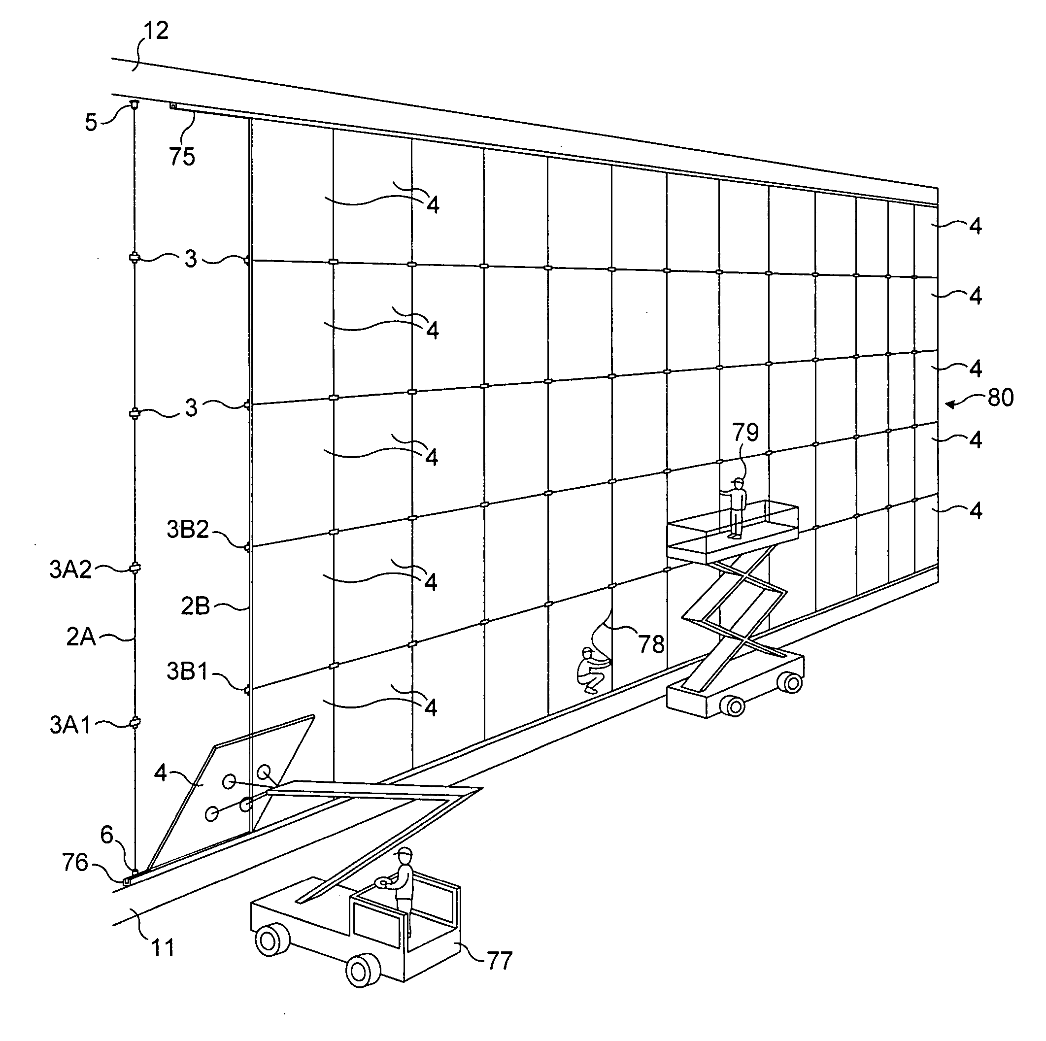
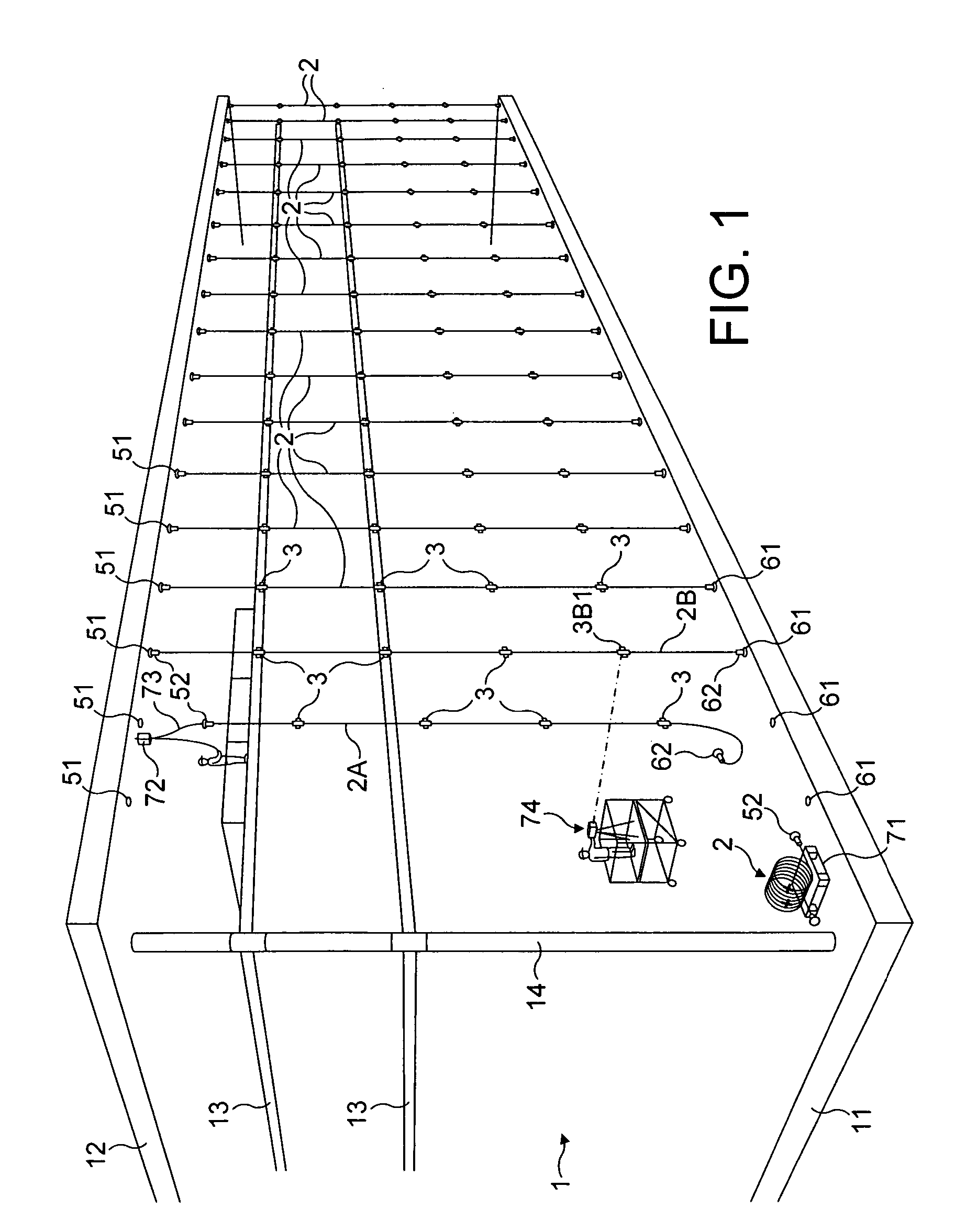
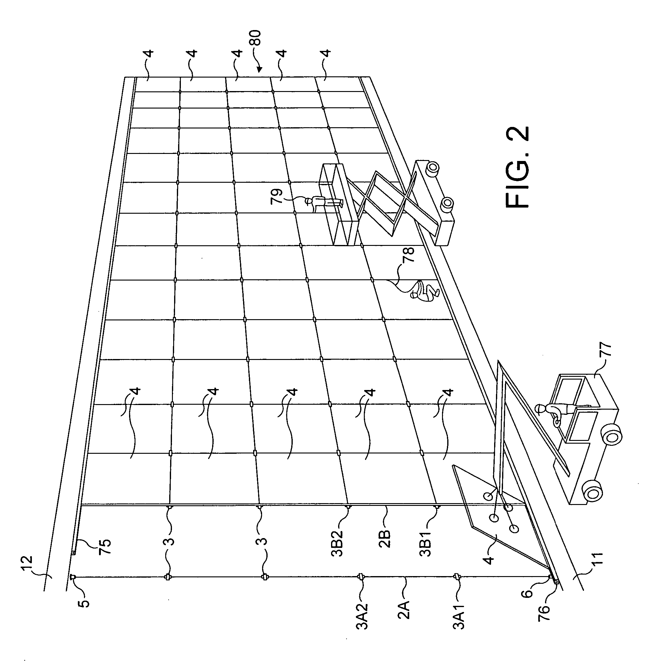
[0110] In relation to the present invention shown in FIGS. 1-10, a building 1 comprises floor slab 11, a roof 12 and intermediate floors 13 supported on columns 14. The illustrated front face of the building is flat and is having a panel system in accordance with the present invention fitted thereto. The end objective is to fit a glazed curtain wall 80 to the front face of the building.
[0111] The panel system comprises fibre linear tensile elements 2, clamping devices 3 and glazing panels 4. Additionally, each fibre linear tensile element 2 has upper and lower termination devices 5, 6 to enable it to be attached to the building 1.
[0112] As shown in FIGS. 3-5, each termination device 5, 6 comprises an anchor bracket 51, 61 which is fixed to the building 1 and an end termination 52, 62 which is fixed to the end of the fibre linear tensile element 2. An adjustment nut 53, 63 enables the position of the end termination 52, 62 to be varied relative to the static position of the anchor b...
second embodiment
[0153] As shown in FIG. 11, the second embodiment includes a monitoring device 81 connected to form monitoring circuits with the optical fibres 23 of the fibre linear tensile elements 2. The optical fibres 23 are connected in parallel, so that any fall-off in tension of a particular fibre linear tensile element 2 may be detected and that particular fibre linear tensile element 2 identified.
third embodiment
[0154] With regard to the third embodiment shown in FIG. 13, there are two curtain walls each using the panel system of the present invention. There is the outer curtain wall 80 and an inner curtain wall 82. Each wall uses glass panels 4, so it is possible to see through both of the walls. Struts 83 extend between the two walls 80, 82 in order to maintain the spacing between the two walls. The struts could also support a walkway positioned in the gap between the two walls, or components (such as lighting, blinds etc.) could be attached to the struts 83 in order to be positioned in the gap between the walls.
[0155] There is an air entrance (not shown) leading into the gap and an air exit (not shown) for ducting air out of the gap, so that overall the gap between the two walls 80, 82 can function as a flue. This may be useful when, for example, the two walls 80, 82 are south-facing because the flue will help to maintain a cool climate within the building in the summer. In other words, ...
PUM
Abstract
Fibre linear tensile elements 2 are strung between the floor slab 11 and the roof 12 of a building 1. Each fibre linear tensile element has a structural core 21 of polymeric fibres or filaments which can accommodate the tensioning of the fibre linear tensile element. The core 21 is covered by a sheath 22 of polymeric material. The fibre linear tensile elements 2 carry clamping devices 3 which enable glass panels 4 to be secured in position. Each clamping device 3 clamps in position the corners of four adjacent panels 4 at a particular connection node of the glass wall 80, as shown in FIG. 6. Gaskets 78 are applied to fill the inter-panel joints.
Each fibre linear tensile element 2 may include a central optical fibre 23 for detecting any reduction in the tension during use. The tension of the fibre linear tensile elements 2 is monitored by a monitoring device 81 which can produce an appropriate alarm signal.
Because of the polymeric structural nature of the fibre linear tensile elements 2, they will permit the curtain wall 80 to flex to some extent and their tensioning will only vary slightly in response to changes in ambient temperature. The polymeric material is also good at resisting surface corrosion.
The fibre linear tensile elements 2 with the clamping devices 3 prefitted are delivered to site on pallets 71, so as to reduce the amount of work required on site. A laser level 74 may be used to ensure that the clamping devices 3 are positioned at their correct heights, before the glass panels 4 are fitted.
Description
TECHNICAL FIELD [0001] The present invention relates to a panel system which may be installed in a building to form, for example, a curtain wall. [0002] The invention also relates to a building incorporating a panel system, a kit of parts for installing a panel skin in or on a building, and a method of installing in or on a building such a kit of parts. BACKGROUND OF THE INVENTION [0003] It is popular for a building to have a curtain wall of glazing panels in order to create a light, environmentally-controlled enclosed space for greater public amenity and security. For example, the facade of an office building may be two or more storeys high, and may be given an exterior curtain wall of glazed panels. The glazed panels are usually rectangular and abut against one another and are formed into rows and columns. They need to be supported in position. A metal framework of tensioned steel cables or rods, quite often incorporating bracing cables, is frequently positioned behind the glazed ...
Claims
Application Information
Patent Timeline
Application Date:The date an application was filed.
Publication Date:The date a patent or application was officially published.
First Publication Date:The earliest publication date of a patent with the same application number.
Issue Date:Publication date of the patent grant document.
PCT Entry Date:The Entry date of PCT National Phase.
Estimated Expiry Date:The statutory expiry date of a patent right according to the Patent Law, and it is the longest term of protection that the patent right can achieve without the termination of the patent right due to other reasons(Term extension factor has been taken into account ).
Invalid Date:Actual expiry date is based on effective date or publication date of legal transaction data of invalid patent.
