Fraction collector for composition analysis

a fraction collector and composition technology, applied in the field of fluid systems, can solve the problems of changing delay time, special calibrant dyes must be injected, and the timing of triggering detectors is not necessarily installed directly upstream, so as to eliminate the timing error of fraction collectors

Inactive Publication Date: 2006-04-13
WATERS TECH CORP
View PDF5 Cites 17 Cited by
  • Summary
  • Abstract
  • Description
  • Claims
  • Application Information

AI Technical Summary

Benefits of technology

[0017] The present invention provides a method and apparatus for controlling fraction collection in an eluent stream flowing from an LC column. A triggering detector recognizes the presence of a target substance above a predetermined threshold level according to characteristics of chromatographic peaks in the eluent stream. A waste stream detector is disposed to detect peaks in the waste stream flowing from a fraction collector. Presence or absence of a peak in the waste stream above a predetermined threshold level indicates whether the peak was properly collected by the fraction collector. Characteristics of peaks detected by the waste stream detector are used to confirm that the target component of the eluent stream was actually collected by the fraction collector and to calibrate the timing of the fraction collector for optimal collection of the target component. Timing calibration depends on recognizing a fraction collector event, opening or closing, in the waste stream detector's signature of a peak. The timing calibration can be automated. There is no requirement for the waste stream detector to be placed close to the fraction collector. The waste stream can be led to any detector located in the purification system package.
[0027] The present invention overcomes the disadvantages of previously known methods by confirming the collection of a target sample in an eluent stream of a liquid chromatography (LC) column. The present invention further overcomes disadvantages of the prior art by optimizing the timing of a fraction collector to minimize the loss of target sample components. Timing information determined using data from the waste stream detector in the present invention allows continuous recalibration of the fraction collector timing.
[0028] The waste stream detector according to the present invention is not necessarily installed near the fraction collector or on the fraction collector dispensing arm, which makes large and rapid motions. Rather, the waste stream detector can be installed remotely from the fraction collector dispensing arm. This allows standard HPLC detectors to be used which operate on any separated peak, and do not require the prior art recourse to a calibrant dye. In addition, such placement overcomes many disadvantages of the prior art by facilitating use of parallel fraction collector dispensing heads with a single multiplexed waste stream detector. Such placement also allows the use of a standard UV detector having tunable wavelengths to detect a variety of compounds being separated. Placement of a detector in the waste stream according to the present invention also allows the use of a single multi-channel detector for both triggering detector and waste stream detector.
[0030] The various embodiments of the present invention also provide advantages over previously known fraction collector techniques by eliminating the need to place a detector at or near the fraction collector, or to inject a calibrant component into the eluent stream. The present invention also eliminates fraction collector timing errors introduced by reliance in the prior art on flow characteristics of a calibrant that may be different from flow characteristics of a desired component at a later time in the eluent stream.

Problems solved by technology

However, the triggering detector is not necessarily installed directly upstream of a fraction collector.
One drawback of this calibration method is that the special calibrant dye must be injected whenever it is desired to check that the correct delay time is being used.
For example, a change in flow rate for any reason will result in a change in delay time, which could go unnoticed.
Such placement is disadvantageous for use because typical fraction collectors use long robotic arms to dispense into collection vessels.
This precludes use of standard HPLC detectors, for example a tunable UV detector, which can be used to detect a variety of components being separated, but are not suitable for mounting on a robotic arm.
Furthermore, the various apparatus described in Fischer '633 and Fischer '710 do not provide confirmation that a desired component was successfully collected by a fraction collector.
The calibrated delay period therefore may include errors that result in non-optimal collection of a desired substance at the fraction collector.
Even small errors in timing can cause a fraction collector to miss much or all of a target substance.
None of the methods and apparatus heretofore known for controlling fraction collector timing in LC systems include a means to confirm the successful collection of a desired component in the eluent stream.

Method used


Image

  • Fraction collector for composition analysis
  • Fraction collector for composition analysis
  • Fraction collector for composition analysis

Examples


Embodiment Construction

[0041] The present invention will be described in detail with respect to chromatographic applications with the understanding that embodiments of the present invention are directed to industrial and process control applications as well.

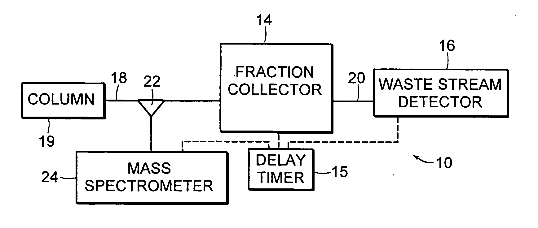
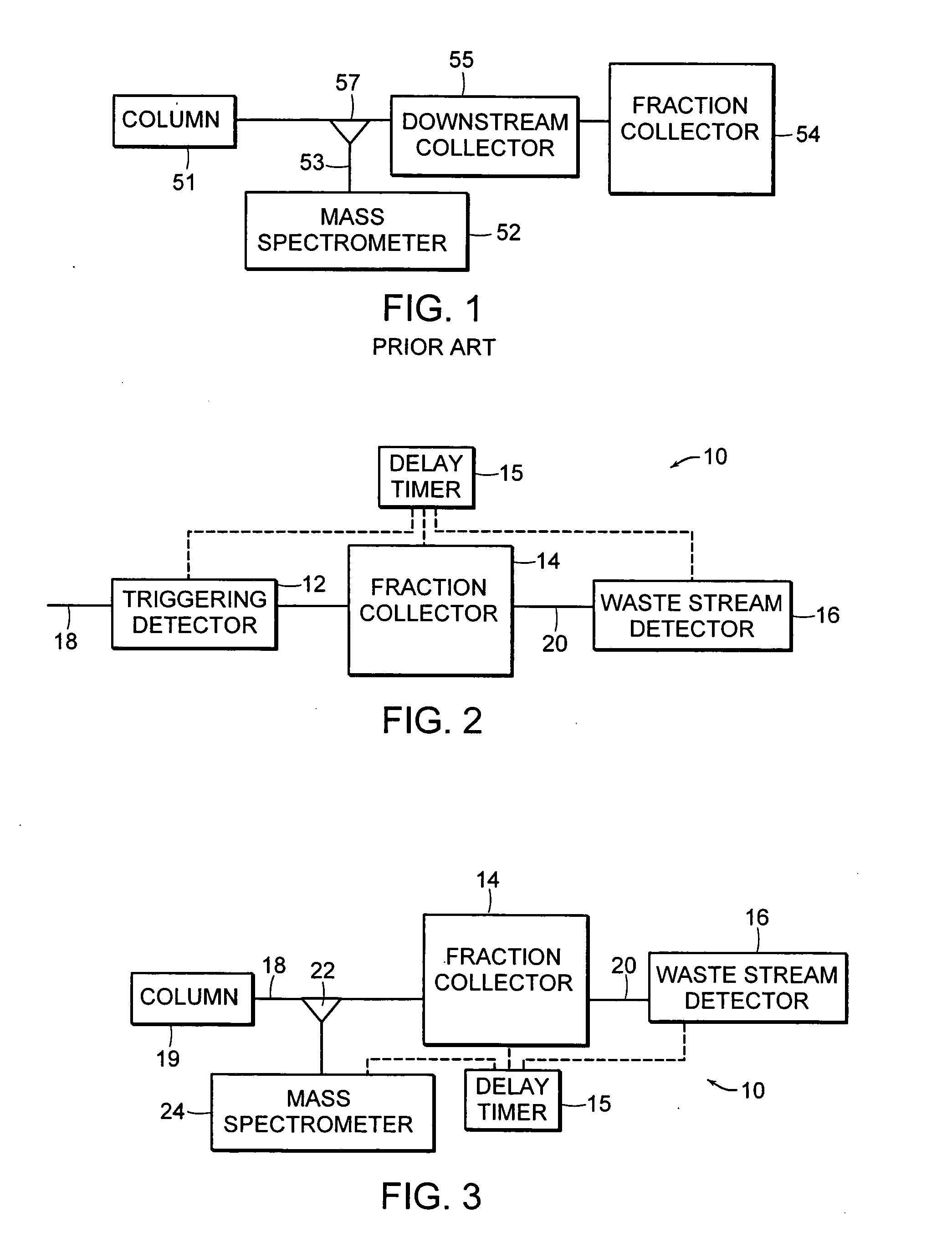
[0042] Referring to FIG. 2, a system flow path 10 according to an illustrative embodiment of the invention is shown diagrammatically. The system flow path 10 includes a triggering detector 12, a fraction collector 14 and a waste stream detector 16 arranged in series. A delay timer 15 is configured to introduce timed signals for actuating (opening and closing) the fraction collector 14. An eluent stream 18 from a liquid chromatography column (LC Column) (not shown) flows through the triggering detector 12 and continues on to the fraction collector 14. The fraction collector 14 is triggered by the delay timer 15 at an appropriate time to divert and collect or identify a particular component of the eluent stream 18. The portions of the eluent stream 18 t...


PUM

PropertyMeasurementUnit
timeaaaaaaaaaa
wavelengthaaaaaaaaaa
time delayaaaaaaaaaa

Abstract

A method and apparatus for controlling fraction collection in an eluent stream flowing from an LC column. A triggering detector recognizes the presence of a target substance according to characteristics of chromatographic peaks in the eluent stream and initiates a delay timer to trigger the fraction collector. A waste stream detector is disposed at any distance from the fraction collector to detect peaks in the waste stream flowing from a fraction collector. The signature of fraction collector actuation is seen by the waste stream detector, permitting the delay time to be adjusted for optimal collection of the target compound. The presence or absence of a peak or the characteristics of a remnant peak detected by the waste stream detector are used to confirm that the target component of the eluent stream was collected as intended by the fraction collector.

Description

REFERENCE TO RELATED APPLICATIONS [0001] This patent application is a Divisional of application Ser. No. 10 / 427,324, filed May 1, 2003 contents of which is incorporated herein by reference in its entirety and claims the benefit thereof.FIELD OF THE INVENTION [0002] This invention relates to a fluid system and particularly to fraction collection in a liquid chromatography (“LC”) eluent stream. BACKGROUND OF THE INVENTION [0003] Liquid chromatography is commonly used for analyzing the composition of chemical compounds whereby solutions containing the compounds to be analyzed are forced under pressure through a liquid chromatography (LC) column. The LC column is specifically constructed to interact with the pressurized solution and affect the fluid flow rate in a way that is characteristic of the composition of chemicals in the solution. Components are thereby separated in the solution according to their chemical composition and corresponding flow rate. Eluent from the LC column is typ...

Claims


Application Information

Patent Timeline
Patent Type & Authority Applications(United States)
IPC IPC(8): G01N1/00G01N30/82G01N30/86
CPCG01N30/82G01N30/8665G01N30/8631
Inventor GILBY, ANTHONYCRAZE, ANDREW SIMON
Owner WATERS TECH CORP
Why Eureka
Try Eureka