Leverage handle

a technology of lever handle and handle handle, which is applied in the direction of wrenches, screwdrivers, manufacturing tools, etc., can solve the problems of difficult to manually achieve significant leverage on the vice handle, relatively difficult, and the section of pipe may readily disengage from the vice handle, etc., to achieve efficient and safe manner, increase the effect of leverag

Inactive Publication Date: 2006-04-13
SNAP JAWS MFG
View PDF14 Cites 5 Cited by
  • Summary
  • Abstract
  • Description
  • Claims
  • Application Information

AI Technical Summary

Benefits of technology

[0006] The present invention therefore provides a hand tool which increases the leverage exerted upon a vice handle in an efficient and safe manner.

Problems solved by technology

Oftentimes, it is difficult to manually achieve significant leverage on the vice handle to exert the desired vice jaw force.
This may be relatively difficult when the vice handle includes a knobbed end.
Furthermore, the section of pipe may readily disengage from the vice handle.

Method used


Image

  • Leverage handle
  • Leverage handle
  • Leverage handle

Examples


Embodiment Construction

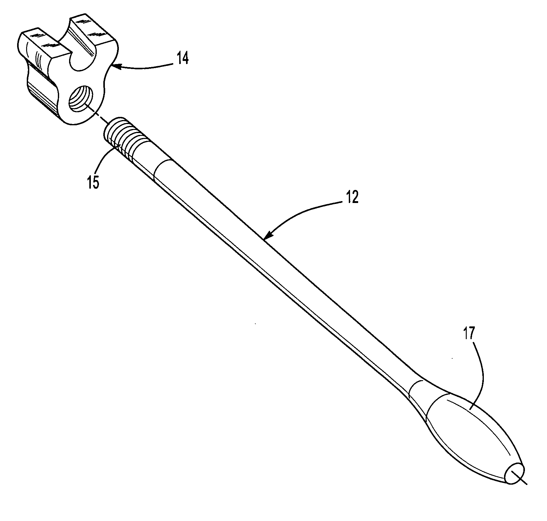
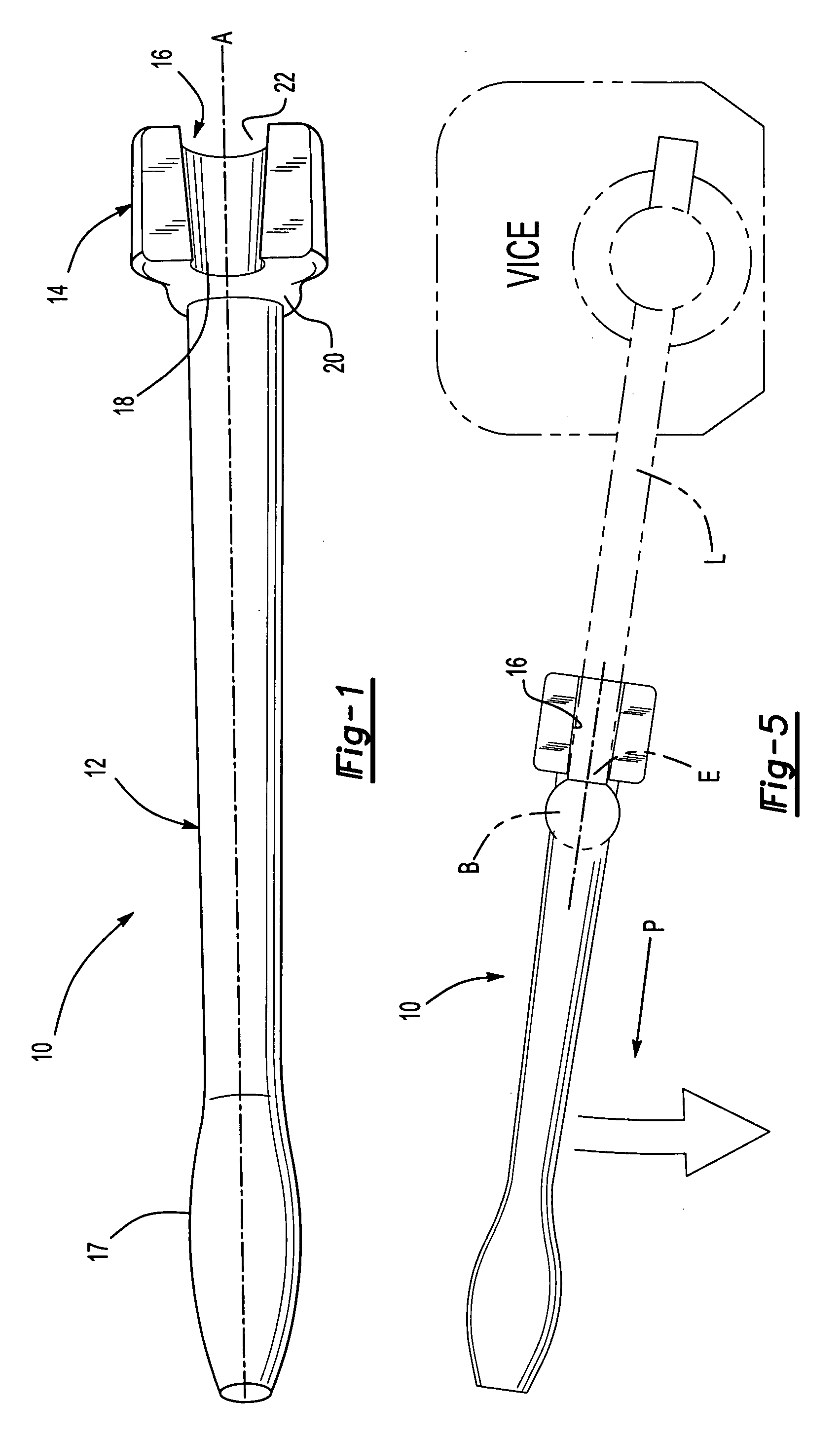
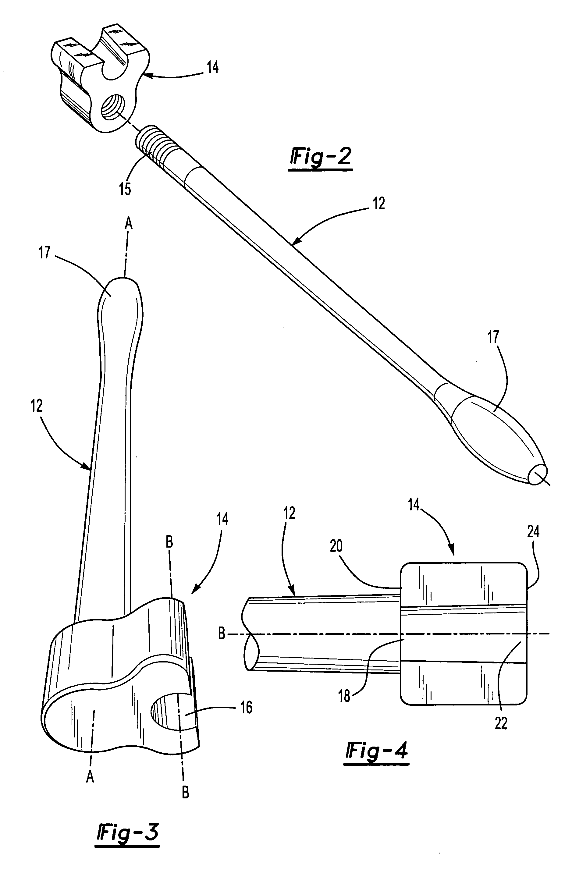
[0013]FIG. 1 illustrates a general perspective view of a leverage handle tool 10. The tool 10 generally includes a handle 12 and a seat block 14. The seat block 14 is mounted to an end section 15 of the handle 12 through, threads, welding or the like (FIG. 2).

[0014] The handle 12 defines a first axis A. The handle 12 includes an enlarged end 17 located opposite the block 14. The handle 12 may alternatively or additionally include a non-slip surface, grip or the like.

[0015] The seat block 14 preferably defines a frusto-conical slot 16 along a slot axis B (FIG. 3). That is, the slot 16 defines a relatively smaller semi-circular opening 18 at a handle end 20 and a relatively larger semi-circular opening 22 at an opposite end 24 of the seat block 14 (FIG. 4). The slot axis B is defined parallel and offset from axis A.

[0016] Referring to FIG. 5, the tool 10 is mounted for use. Generally, the slot 16 is located upon a handle L, such as a vice handle, and the tool 10 is pulled toward th...


PUM


Abstract

A leverage handle tool includes a handle and a seat block. In use, a slot in the seat block is located upon a handle such as a vice handle, and the tool is pulled toward the handle end. As the tool is pulled toward the handle end the slot grips the handle due to the frusto-conical configuration thereof. The tool may then be acted upon such that the tool increase the leverage upon handle.

Description

BACKGROUND OF THE INVENTION [0001] The present invention relates to a hand tool, and more particularly to a leverage increasing hand tool for a vice. [0002] Vices are long known for holding work pieces during shaping, cutting, finishing, and the like. Other vice jaws are incorporated into machine tools to receive a workpiece. The vice typically utilizes an extended handle, which is rotated to close the vice and retain the workpiece. Oftentimes, it is difficult to manually achieve significant leverage on the vice handle to exert the desired vice jaw force. Machinists and others have often utilized a section of pipe to increase the leverage on the vice handle. This may be relatively difficult when the vice handle includes a knobbed end. Furthermore, the section of pipe may readily disengage from the vice handle. [0003] Accordingly, it is desirable to provide a hand tool which increases the leverage that is exerted upon a vice handle in an efficient and safe manner. SUMMARY OF THE INVE...

Claims


Application Information

Patent Timeline
Patent Type & Authority Applications(United States)
IPC IPC(8): B25B23/16
CPCB25G1/043
Inventor FITZPATRICK, JOHN P.
Owner SNAP JAWS MFG
Why Eureka
Try Eureka