Thermoelectric device structure and apparatus incorporating same

Inactive Publication Date: 2006-04-13
NANOCOOLERS
View PDF99 Cites 93 Cited by
  • Summary
  • Abstract
  • Description
  • Claims
  • Application Information

AI Technical Summary

Benefits of technology

[0011] A complementary, lateral, thermoelectric device structure is provided. Such a device may include thermoelectric elements of opposing conductivity types coupled electrically in series and therm

Problems solved by technology

If the heat is not dissipated, it may adversely affect the performance of these devices.
Such passive cooling methods may provide limited cooling capacity due to spatial limitations.
Because of the large required volume, moving mechanical parts, poor reliability and associated

Method used


Image

  • Thermoelectric device structure and apparatus incorporating same
  • Thermoelectric device structure and apparatus incorporating same
  • Thermoelectric device structure and apparatus incorporating same

Examples


Example

[0066] The use of the same reference symbols in different drawings indicates similar or identical items.

DETAILED DESCRIPTION

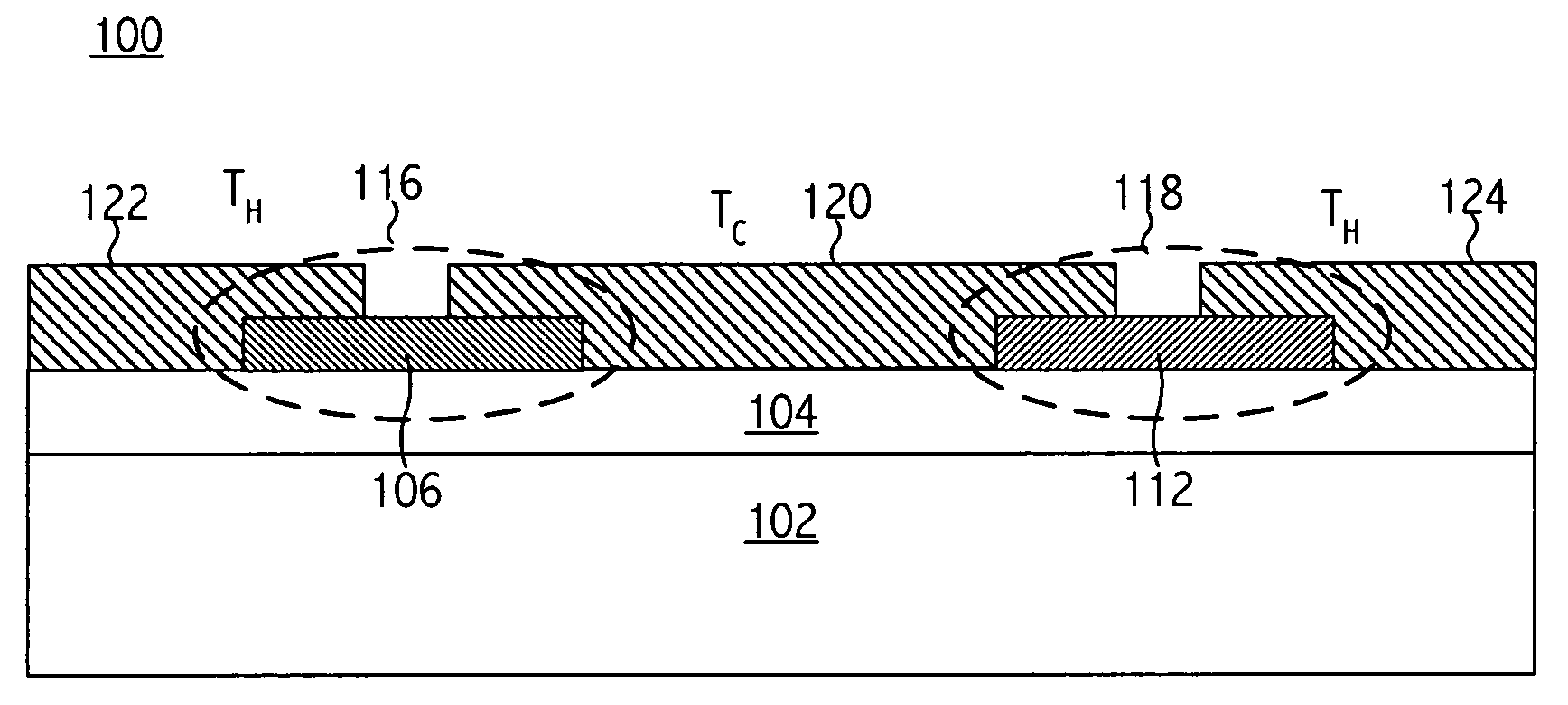
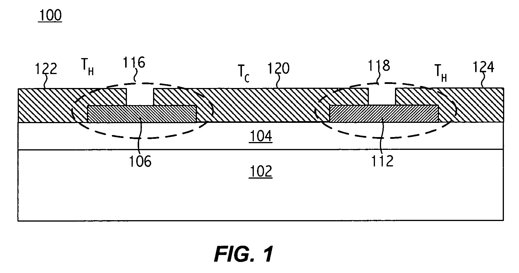
[0067] Referring now to FIG. 1, an exemplary lateral complementary thermoelectric device 100 includes three electrodes 122, 120, and 124 formed on the same side of a substrate 102. A low thermal conductivity layer 104 is formed on the substrate 102 to reduce heat conduction via the substrate 102 of the device. The layer 104 may also function as an etch stop layer. The substrate 102 and any optional overlayers (e.g., layer 104) act as a supporting structure for the thermoelectric device.

[0068] A thermoelectric element 106 of a first type (e.g., n-TE material) and a thermoelectric element 112 of a second type (e.g., p-TE material) are formed on the low conductivity layer 104 (i.e., the upper surface of the supporting structure). The electrode 122 overlaps and makes electrical and thermal contact to the thermoelectric element 106, the electrode 120 overlaps and...


PUM


Abstract

In certain embodiments, a thermoelectric device apparatus includes a plurality of laterally spaced-apart electrodes disposed upon a supporting structure, and at least one complementary pair of thermoelectric elements, each thermoelectric element coupling an electrode to a laterally adjacent electrode. Such a structure reduces the need for solder joints or other structures or mechanisms to attach multiple substrates, components, or assemblies together to form a thermoelectric device.

Description

CROSS-REFERENCE TO RELATED APPLICATION(S) [0001] This application claims the benefit under 35 U.S.C. § 119(e) of U.S. Provisional Application No. 60 / 617,513, filed Oct. 8, 2004, entitled “MONOLITHIC THIN-FILM THERMOELECTRIC DEVICE INCLUDING COMPLEMENTARY THERMOELECTRIC MATERIALS” by Srikanth B. Samavedam, et al., which application is hereby incorporated by reference. [0002] This application claims the benefit under 35 U.S.C. § 119(e) of U.S. Provisional Application No. 60 / 649,273, filed Feb. 2, 2005, entitled “LATERAL THERMOELECTRIC DEVICE STRUCTURE AND RELATED APPARATUS” by Uttam Ghoshal, et al., which application is hereby incorporated by reference. [0003] This application claims the benefit under 35 U.S.C. § 119(e) of U.S. Provisional Application No. 60 / 659,541, filed Mar. 8, 2005, entitled “LATERAL THERMOELECTRIC DEVICE STRUCTURE AND RELATED APPARATUS” by Uttam Ghoshal, et al., which application is hereby incorporated by reference.BACKGROUND [0004] 1. Field of the Invention [000...

Claims


Application Information

Patent Timeline
IPC IPC(8): H01L35/30H01L35/28
CPCH01L27/16H01L35/32H10N19/00H10N10/17
Inventor GHOSHAL, UTTAMNGAI, TATSAMAVEDAM, SRIKANTH B.YE, ZHENGMAOMINER, ANDREW C.
Owner NANOCOOLERS
Why Eureka
Try Eureka