
High pressure quick connect coupling and seal

a quick connection, coupling technology, applied in the direction of hose connection, fluid pressure sealing joint, pipe-joint, etc., can solve the problems of large wrench, damaged couplings, and large physical effort to connect and disconnect, so as to achieve quick and easy connection and minimal physical effort

Inactive Publication Date: 2006-04-13
HILOSEAL TECH LLC
View PDF20 Cites 1 Cited by
  • Summary
  • Abstract
  • Description
  • Claims
  • Application Information

AI Technical Summary

Benefits of technology

The present invention provides a quick connect pipe coupling and seal assembly that is resistant to corrosion and can be easily connected and disconnected with minimal physical effort. The assembly includes a cylindrical coupling head with a threaded bore for connection to a hose or pipe, an annular ring with a curved outer edge, and a cylindrical coupling ring for holding the first coupling head captive. The coupling ring has external male threads for connection to the second coupling head, which holds an O-ring in its annular recess. The O-ring forms a high pressure seal between the first and second coupling heads. The assembly also includes handles for quickly connecting and disconnecting the first coupling head from the second coupling head.

Problems solved by technology

Many pipe and hose couplings require large wrenches and great physical effort to connect and disconnect high pressure vessels to reservoirs for the high pressure fluids contained in the high pressure vessels.
Many of the fluids in the high pressure vessels are corrosive and can cause damage to the couplings of the prior art and sometimes render the couplings of the prior art unusable in a short period of time, and damaged couplings may leak dangerous fluids to the environment.
Furthermore, couplings damaged due to corrosion could explode and result in serious injury to persons and property in the vicinity of the explosion, and pollute the surrounding area with toxic chemicals.
Chlorine gas is an example of a widely used industrial gas stored under high pressure which is toxic to humans and can cause damage to the environment, and which is very corrosive to common pipe couplings.

Method used


Image

  • High pressure quick connect coupling and seal
  • High pressure quick connect coupling and seal
  • High pressure quick connect coupling and seal

Examples


Embodiment Construction

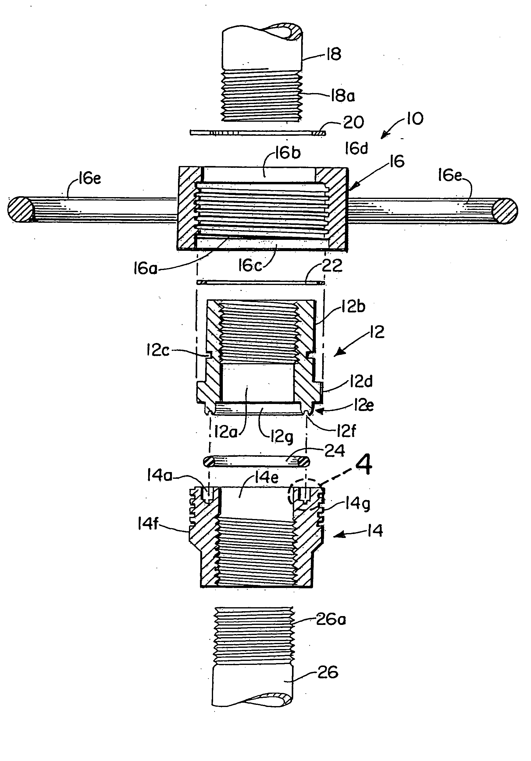
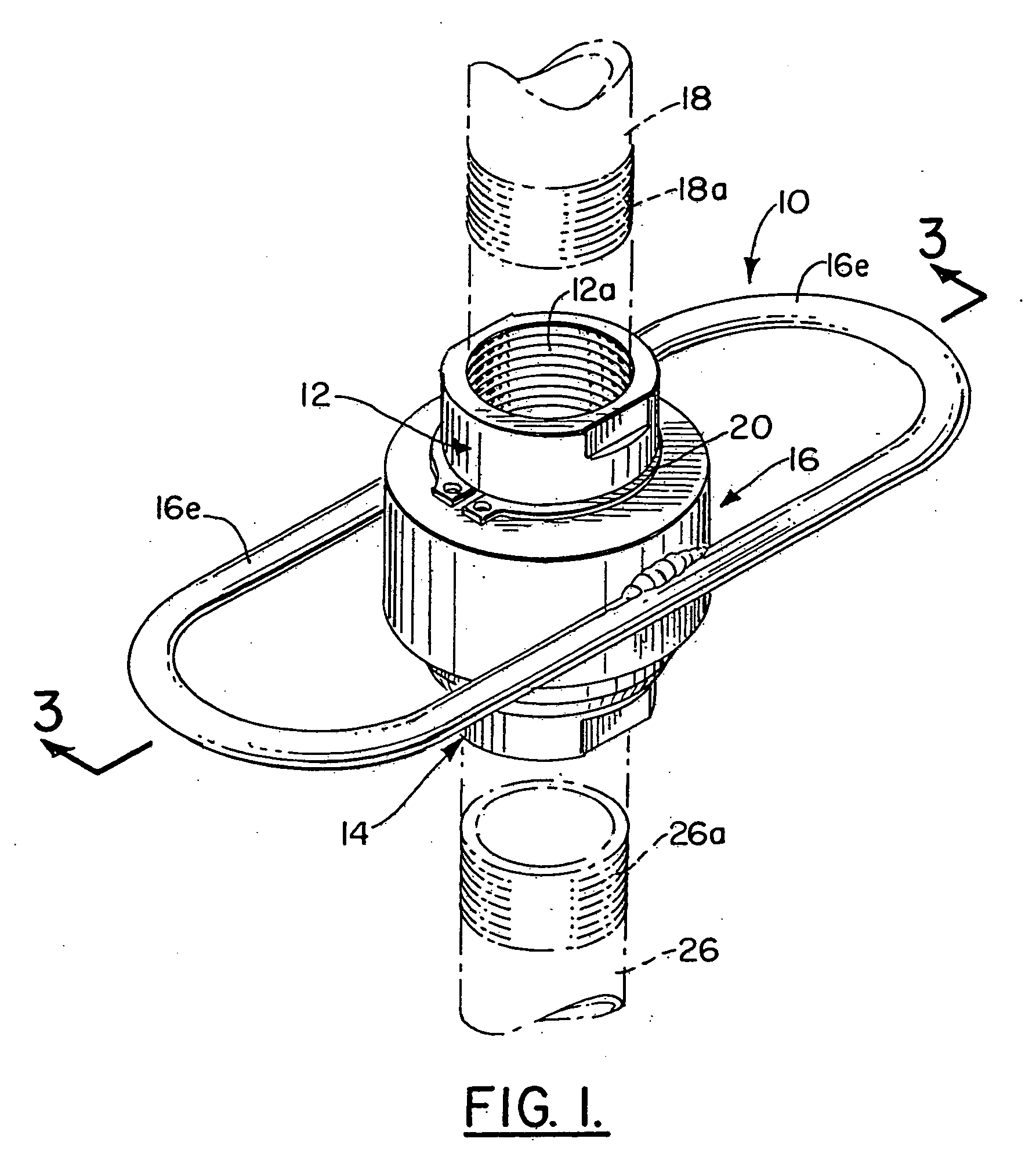
[0017] Referring now to the drawings, and in particular to FIG. 1, the quick connect coupling assembly of the invention is generally indicated by the numeral 10. Coupling assembly 10 includes a first coupling head generally indicated by the numeral 12, a second coupling head generally indicated by the numeral 14, and a coupling ring generally indicated by the numeral 16. The coupling heads 12 and 14, snap ring 20, and the coupling ring 16, are constructed from corrosion resistant materials.

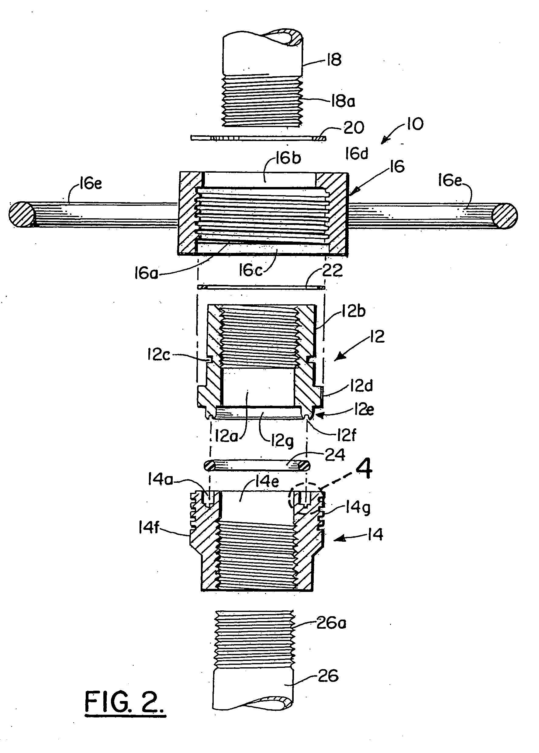
[0018] As shown in FIGS. 1-3, coupling head 12 is generally cylindrical in shape and has female threads 12a surrounding a female threaded central bore 12a for receipt of the male threads 18a on pipe 18. Coupling head 12 has a cylindrical outer wall 12b having a circular slot 12c axially aligned therewith extending therearound for receipt of snap ring 20. Snap ring 20 is a conventional metal snap ring well known in the art which functions to hold coupling head 12 inside coupling ring 16 when coupl...


PUM


Abstract

A quick connect and disconnect pipe coupling and seal assembly including a first generally cylindrical coupling head having a bore therein for connection to a first conduit and a raised annular ring, a second generally cylindrical coupling head having a bore therein for connection to a second conduit, external male threads, and an annular recess for receiving an o-ring, and a generally cylindrical coupling ring for holding the first coupling head therein, the coupling ring having a threaded bore for receipt of the external male threads of the second coupling head to connect the first coupling head to the second coupling head and to force the o-ring received in the annular recess of the second coupling head into contact with the annular ring on the first coupling head to form a high pressure seal between the first coupling head and the second coupling head.

Description

REFERENCE TO RELATED APPLICATION [0001] This is a continuation of co-owned and co-pending U.S. patent application Ser. No. 10 / 452,268, filed on Jun. 2, 2003, the entire disclosure of which is incorporated herein by reference.BACKGROUND OF THE INVENTION [0002] 1. Field of the Invention [0003] The present invention relates to quick connect couplings. More particularly, the invention is related to quick connect couplings for high pressure pipes and hoses. [0004] 2. Description of the Related Art [0005] Pipe coupling assemblies are widely used in the art to convey liquids and gases under pressure to various reservoirs. High pressure storage vessels and tank trucks employ quick connect pipe couplings to connect pipe and hoses to a high pressure vessel to discharge fluids from the high pressure vessel to desired tanks and reservoirs. [0006] Many pipe and hose couplings require large wrenches and great physical effort to connect and disconnect high pressure vessels to reservoirs for the hi...

Claims


Application Information

Patent Timeline
Patent Type & Authority Applications(United States)
IPC IPC(8): F16L19/00F16L19/02
CPCF16L19/0218F16L19/0231
Inventor COOKE, CHARLES M. JR.
Owner HILOSEAL TECH LLC
Learn More