Low power high frequency phase detector

Inactive Publication Date: 2006-04-13
IBM CORP
View PDF4 Cites 8 Cited by
  • Summary
  • Abstract
  • Description
  • Claims
  • Application Information

AI Technical Summary

Benefits of technology

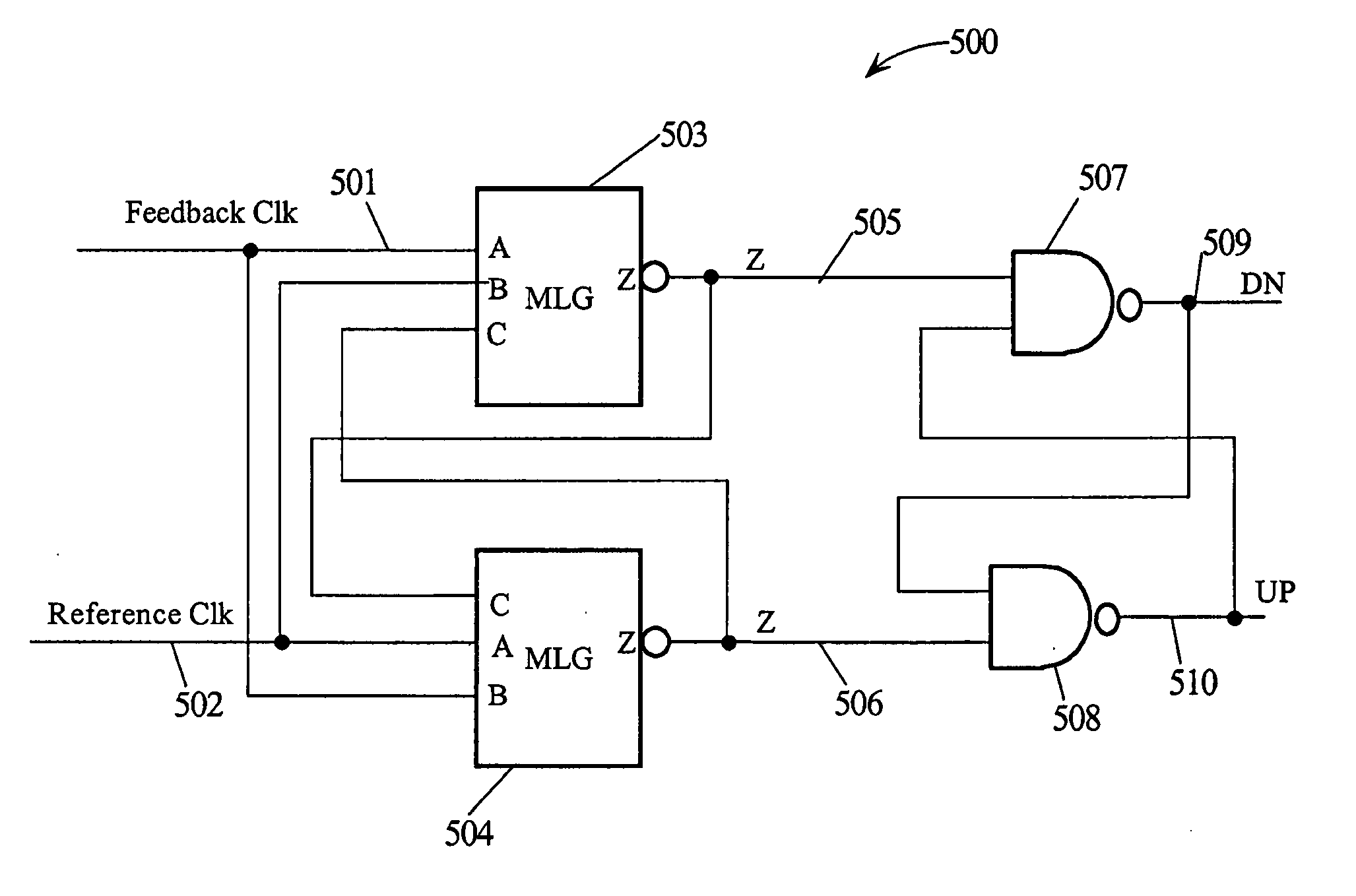
[0012] The first and second MLGs have input states wherein the output is in a floating condition. When the “A” input is a logic one, the “B” input is a logic zero, and the “C” input is a logic one, the output of the first and second MLGs float for a short duration.
[0013] In another embodiment of the present invention, another pull-down device controlled by the “A” input is added in paral

Problems solved by technology

The higher the clock frequency the more this is a problem.
If clocks cannot be aligned, then the clock frequency in a synchronous system may be high frequency limited.
However, if the clocks are high frequen

Method used


Image

  • Low power high frequency phase detector
  • Low power high frequency phase detector
  • Low power high frequency phase detector

Examples


Example

[0029] In the following description, numerous specific details are set forth to provide a thorough understanding of the present invention. However, it will be obvious to those skilled in the art that the present invention may be practiced without such specific details. In other instances, well-known circuits may be shown in block diagram form in order not to obscure the present invention in unnecessary detail. For the most part, details concerning timing, and the like have been omitted inasmuch as such details are not necessary to obtain a complete understanding of the present invention and are within the skills of persons of ordinary skill in the relevant art.

[0030] Refer now to the drawings wherein depicted elements are not necessarily shown to scale and wherein like or similar elements are designated by the same reference numeral through the several views.

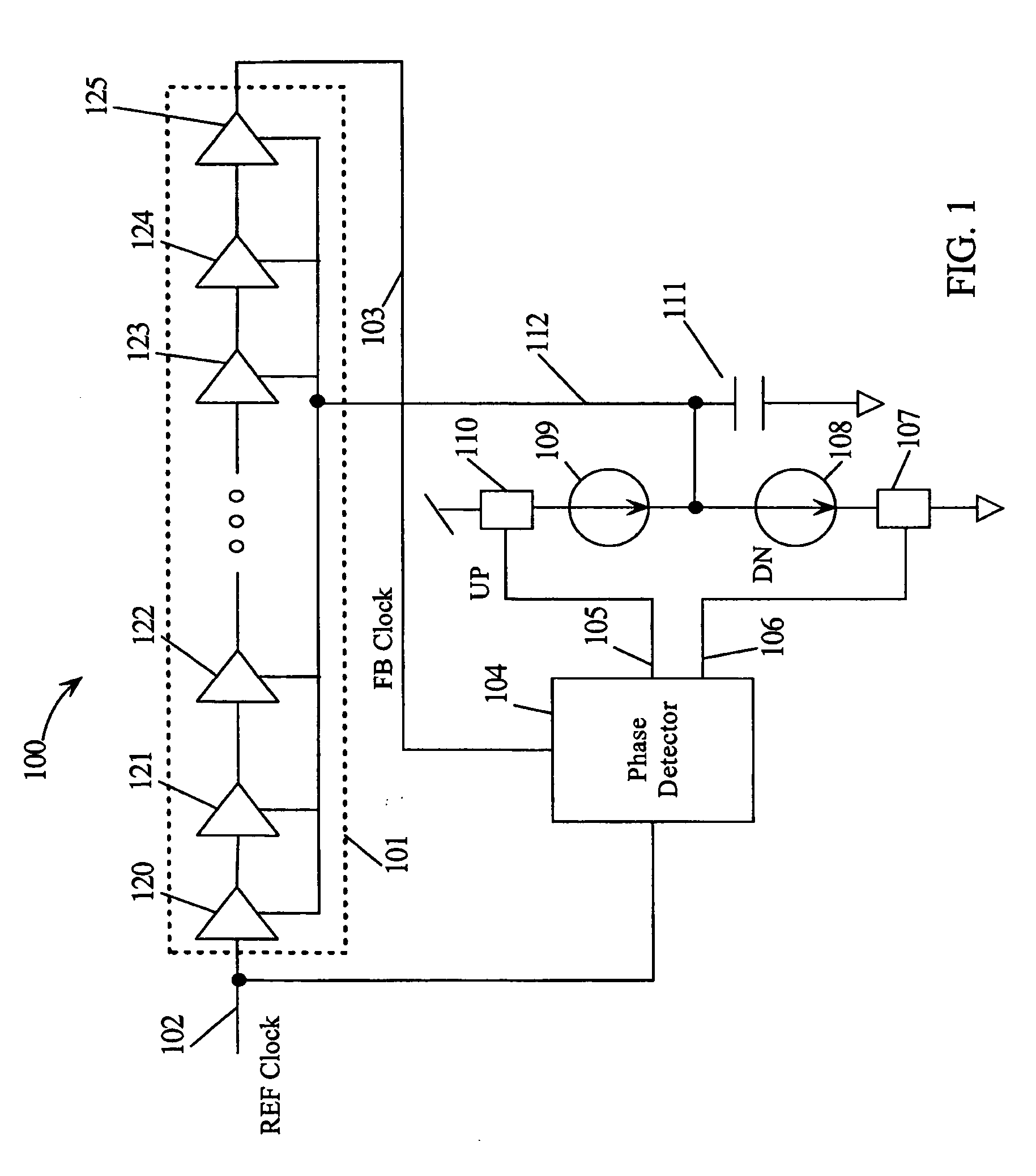
[0031]FIG. 1 is a block diagram of DLL circuitry used to generate a feedback (FB) clock 103 that is in phase with a referenc...


PUM


Abstract

A phase detector employs a modified logic gate in conjunction with a set/reset latch to make a phase detector that generates control outputs for use in increasing and decreasing the delay in a delay circuit in the path of a feedback clock generated by delaying a reference clock. The delay circuit provides a controllable delay from less than to greater than one clock cycle of the reference clock. The phase detector generates an up control (UP) signal for increasing delay when the feedback clock leads the reference clock and a down control (DN) signal for decreasing delay when the feedback clock lags the reference clock. The UP signal and DN signal are updated each clock cycle when the leading clock edge makes a transition.

Description

TECHNICAL FIELD [0001] The present invention relates in general to phase detectors and, in particular, to phase detectors used in delay locked loops (DLL). BACKGROUND INFORMATION [0002] A phase locked loop (PLL) or a DLL both require a phase detector as a fundamental functional block. The PLL utilizes the phase detector with a voltage controlled oscillator (VCO) to generate high frequencies that are a multiple of a reference clock that is generated to have a stable frequency. The output of the VCO is frequency divided to generate a divided clock. The divided clock is phase compared with the reference clock thereby generating an error signal. The error signal is used to control the VCO. Increasing the VCO frequency makes transitions occur earlier and decreasing the VCO frequency makes transitions occur later relative to the reference frequency. Using a phase comparator and the VCO in this manner allows the divided frequency to phase lock with the reference frequency when in a closed ...

Claims


Application Information

Patent Timeline
IPC IPC(8): H03L7/06
CPCH03D13/004H03L7/0812H03L7/089H03L7/0891H03L7/0816
Inventor YOO, SEUNG-MOONNGO, HUNG C.
Owner IBM CORP
Why Eureka
Try Eureka