

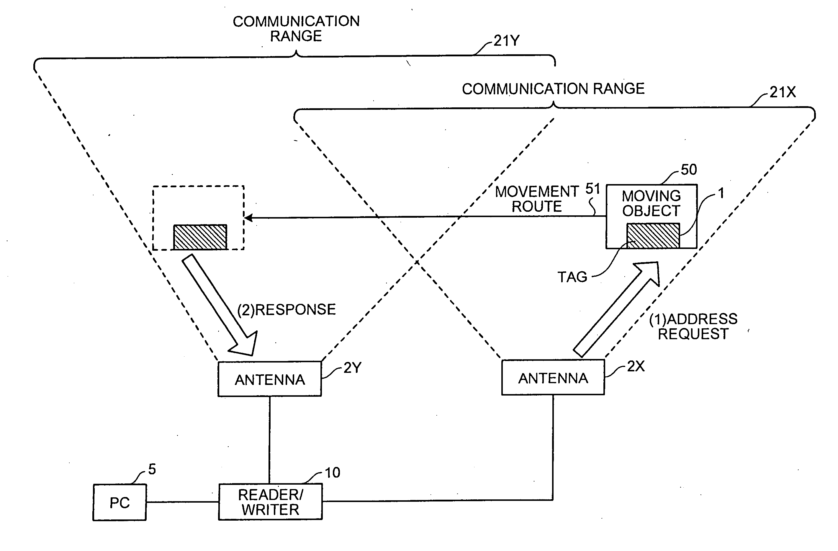
Reader/writer and RFID system
a technology of rfid system and reader, which is applied in the direction of fishing, burglar alarm mechanical actuation, instruments, etc., can solve the problems of tag disappearance from the readable area, difficult reading/writing of tag attached to moving objects, and shorter reading tim
- Summary
- Abstract
- Description
- Claims
- Application Information
AI Technical Summary
Benefits of technology
Problems solved by technology
Method used
Image

Examples
first embodiment
[0070]FIG. 3 is a block diagram of the reader / writer according to the The reader / writer 10 includes a Micro Processing Unit (MPU) 11, a transmitting unit 12, a receiving unit 13, a signal dividing / combining unit (signal processing unit) 14, the antennas 2X to 2Z, and a controlling unit 19.
[0071] The MPU 11 is a very small computing device for controlling the information to be read from and written into the tag 1 via the antennas 2X to 2Z, and transmits predetermined command information to the controlling unit 19 in accordance with the command information from the PC 5.
[0072] The transmitting unit 12 transmits predetermined information (a command) (communication data) to be written into the tag 1 on the basis of the command information from the controlling unit 19 by the RFID. The receiving unit 13 receives predetermined information from the tag 1 by the RFID.
[0073] The signal dividing / combining unit 14 divides predetermined information (signal) sent from the transmitting unit 12 ...
second embodiment
[0141] Next, the present invention is now explained with reference to FIGS. 13 to 15.
[0142] In this second embodiment, the communication range of an antenna is extended by rotating the antenna of the reader / writer 10 or driving it in a similar way. The antenna is rotated in such a manner that the communication range of the antenna follows the movement of the moving object 50.
[0143]FIG. 13 is a schematic for explaining the concept of an RFID system according to the second embodiment; and FIG. 14 is a block diagram of the reader / writer according to the second embodiment. Among the constituent members in these FIGS. 13 and 14, the members having the same functions as those of the RFID system and the reader / writer 10 of the first embodiment shown in FIGS. 2 and 3 are assigned the same reference signs in order to omit repetition of the same explanation.
[0144] The RFID system includes the PC 5, a reader / writer 30, an antenna 2R, and the tag 1 attached to the moving object 50. The antenn...
third embodiment
[0156] Next, the present invention is now explained with reference to FIGS. 16 to 21.
[0157] A RFID system according to a third embodiment includes a first reader / writer 41 for identifying the sequence of the tags, and a second reader / writer 42A for carrying out the read / write operations.
[0158]FIG. 16 illustrates is the RFID system according to the third embodiment. FIG. 17 is a block diagram of the reader / writer 41 that identifies the sequence of the tags 1. FIG. 18 is a block diagram of the reader / writer 42A that performs the reading / writing operations from / to the tags 1. Among the constituent members in these FIGS. 16 to 18, the members having the same functions as those of the RFID system and the reader / writer 10 of the first embodiment shown in FIGS. 2 and 3 are assigned the same reference signs in order to omit repetition of the same explanation.
[0159] As shown is FIG. 16, the RFID system includes the PC 5, the reader / writer 41 and the reader / writer 42A (hereinafter a plurali...
PUM
 Abstract
Description
Claims
Application Information