

Obstacle detection device
a detection device and obstacle technology, applied in the direction of vehicle position/course/altitude control, process and machine control, instruments, etc., can solve the problems of not not not not alerting the driver of such a situation, the second device still has and the possibility of reducing the possibility of bothering the driver. , to achieve the effect of reducing the possibility of bothering the driver
- Summary
- Abstract
- Description
- Claims
- Application Information
AI Technical Summary
Benefits of technology
Problems solved by technology
Method used
Image

Examples
modification 1
[0062] (Modification 1)
[0063] The processing unit 10 may always make the notification device 20 notify by sound while the relative velocity exceeds the threshold velocity VT. Thus, the driver is notified the driver more intensively of the obstacle approaching rapidly. Specifically, as shown in FIG. 7, the processing unit 10 may make notification device 20 produce multiple sets of discrete sounds with short duration and short intervals, wherein each set is produced periodically. In this case the processing unit 10 executes the NOTIFICATION process according to the flowchart in FIG. 8 which is different from the flowchart in FIG. 5 in that step S207 is omitted. Thus, if the determination of step S204 is YES, the processing unit 10 always makes the notification device 20 notify the driver of the obstacle approaching rapidly (see steps S204 and S208). Thus, as shown in FIG. 9, the processing unit 10 may make notification device 20 produce sounds regularly from time tzy while the relativ...
modification 2
[0064] (Modification 2)
[0065] The processing unit 10 may calculate acceleration of the obstacle relative to the vehicle at S203 in place of the relative velocity, and determine at step S204 whether the relative acceleration is larger than an acceleration threshold. Thus, the processing unit 10 may determine whether the obstacle is rapidly approaching according to the relative acceleration.
[0066] Moreover, the processing unit 10 may determine whether the obstacle is approaching rapidly according to velocity or acceleration of the vehicle relative to the ground (hereafter absolute velocity or absolute acceleration, respectively). This method of determination works better when the obstacle is not moving. Besides, in many cases, the absolute velocity or the absolute acceleration can be calculated more exactly than the relative velocity or the relative acceleration which is obtained through time derivative and sensitive to fluctuations in the ultrasonic wave.
[0067] In this case, the pr...
modification 3
[0068] (Modification 3)
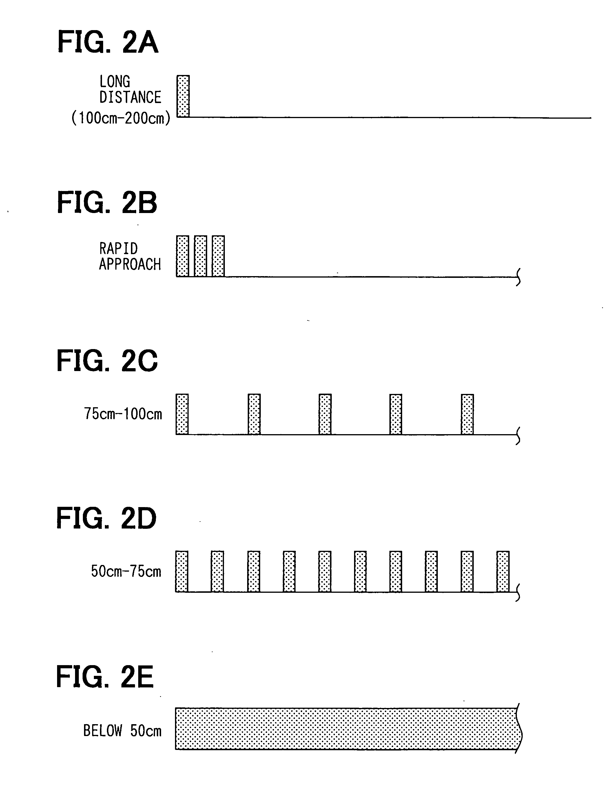
[0069] The obstacle detection device of the above embodiment may accept various adjustments made by the driver. For example, the threshold to distinguish the long distance range and the short distance range can be adjusted by the driver according to the driver's preference. In addition, the processing unit 10 may accept the driver's adjustment regarding sub-thresholds (50, 75 and 100 cm in the above embodiment) to divide the short distance range into three to change the methods of the notification according to the sub-thresholds. In addition, the threshold velocity VT may be adjusted by the driver according to the driver's preference.
[0070] In this case, as shown in FIG. 11, the obstacle detection device may have a Human Machine Interface (HMI) 40 and the processing unit 10 may have a storage device to memorize the adjustments the driver has made by means of the HMI 40. Thus, the device can make the notification in accordance with the driver's preferences.
[0...
PUM
 Abstract
Description
Claims
Application Information