Antenna device for vehicle

a technology for antennas and vehicles, applied in antennas, slot antennas, basic electric elements, etc., can solve the problems of easy displacement in the relative position between, complicated connection work, and easy connection defects, so as to prevent soldering cracks, reduce stress applied to the front end of the power feeding member, and prevent soldering cracks

Inactive Publication Date: 2006-04-13
ALPS ALPINE CO LTD
View PDF7 Cites 20 Cited by
  • Summary
  • Abstract
  • Description
  • Claims
  • Application Information

AI Technical Summary

Benefits of technology

[0010] In this way, when the power feeding member is formed of a band-shaped metal piece extending from the metal plate in which the radiation slots are formed, and a hinge-shaped bent portion is formed in the power feeding member in advance, although displacement is generated in a relative position between the metal plate (the base end side of the power feeding member) and the circuit board (the front end side of the power feeding member) by external vibration and thermal expansion, the displacement can be absorbed by elasticity of the bent portion or the like. Thus, stress applied on the soldered portion of the front end of the power feeding member is decreased, thus preventing soldering cracks from being generated. In addition, since the base end side of the power feeding member is continuous to the metal plate, soldering is not required. Therefore, poor soldering connection of the power feeding member due to external vibration and thermal expansion can be effectively prevented. Thus, assembly efficiency can be improved because soldering connection work in the power feeding member can be made simple.
[0011] In the antenna device having the above-mentioned structure, for example, a portion extending from the base end of the power feeding member to the bent portion thereof is formed of a horizontal portion which extends along a bent line or a curved line which is substantially parallel to the circuit board. Further, a portion extending from the bent portion of the power feeding member to the front and thereof is formed of a drooping portion which extends along a line which is substantially vertical to the circuit board. In this case, if a thickwise direction of the drooping portion is set as an X direction, a direction which is parallel to the circuit board and orthogonal to the X direction is set as a Y direction, and a direction vertical to the circuit board is set as a Z-direction, since the power feeding member has sufficient elasticity with respect to external force opening and closing the hinge-shaped bent portion, although displacement is generated in a relative position between the base end and the front end of the power feeding member in the X direction or the Z direction, the power feeding member easily responds to the displacement. Further, with respect to displacement in the Y-direction, the power feeding member can correspond to the displacement by using torsion of the horizontal portion which extends along the bent line or the curved line. Therefore, although displacement is generated in the relative position between the base end and the front end of the power feeding member in any of the X, Y, and Z directions by external vibration and thermal expansion, stress applied on a soldered portion of the power feeding member can be decreased.
[0012] In addition, in the antenna device having the above-mentioned structure, when the metal plate is an upper plate of a shield case which covers the circuit board, the number of components and assembly processes can be decreased because a slot antenna also serves as a shield case, thereby obtaining a small-sized and inexpensive antenna device. In this case, before a reflow soldering process of mounting various chip components constituting high frequency circuits on the circuit board, the shield case is mounted on the circuit board such that the front end of the power feeding member is mounted on cream solder of a land. Thus, complex soldering connection work is not required for the power feeding member because the power feeding member can be collectively subjected to reflow soldering together with the various chip components.

Problems solved by technology

Thus, solder connection work is not only complicated but also may cause connection defects due to excessively strong stress applied on a soldered portion of the power feeding member, when displacement is generated in a relative position between the upper plate 1a and the circuit board.
In particular, when this type of an antenna device is mounted in a vehicle, displacement may easily occur in the relative position between the upper plate 1a and the circuit board due to thermal expansion which is caused by external vibration and temperature changes.
Thus, for example, whenever the distance between the upper plate 1a and the circuit board increases and decreases, strong stress is applied on the soldered portion of the power feeding member, thus causing soldering crack to easily occur.

Method used


Image

  • Antenna device for vehicle
  • Antenna device for vehicle
  • Antenna device for vehicle

Examples


Embodiment Construction

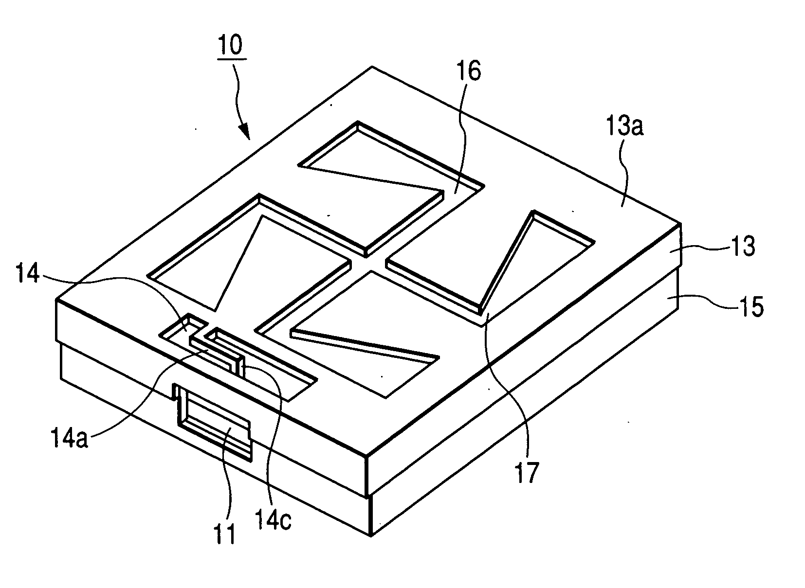
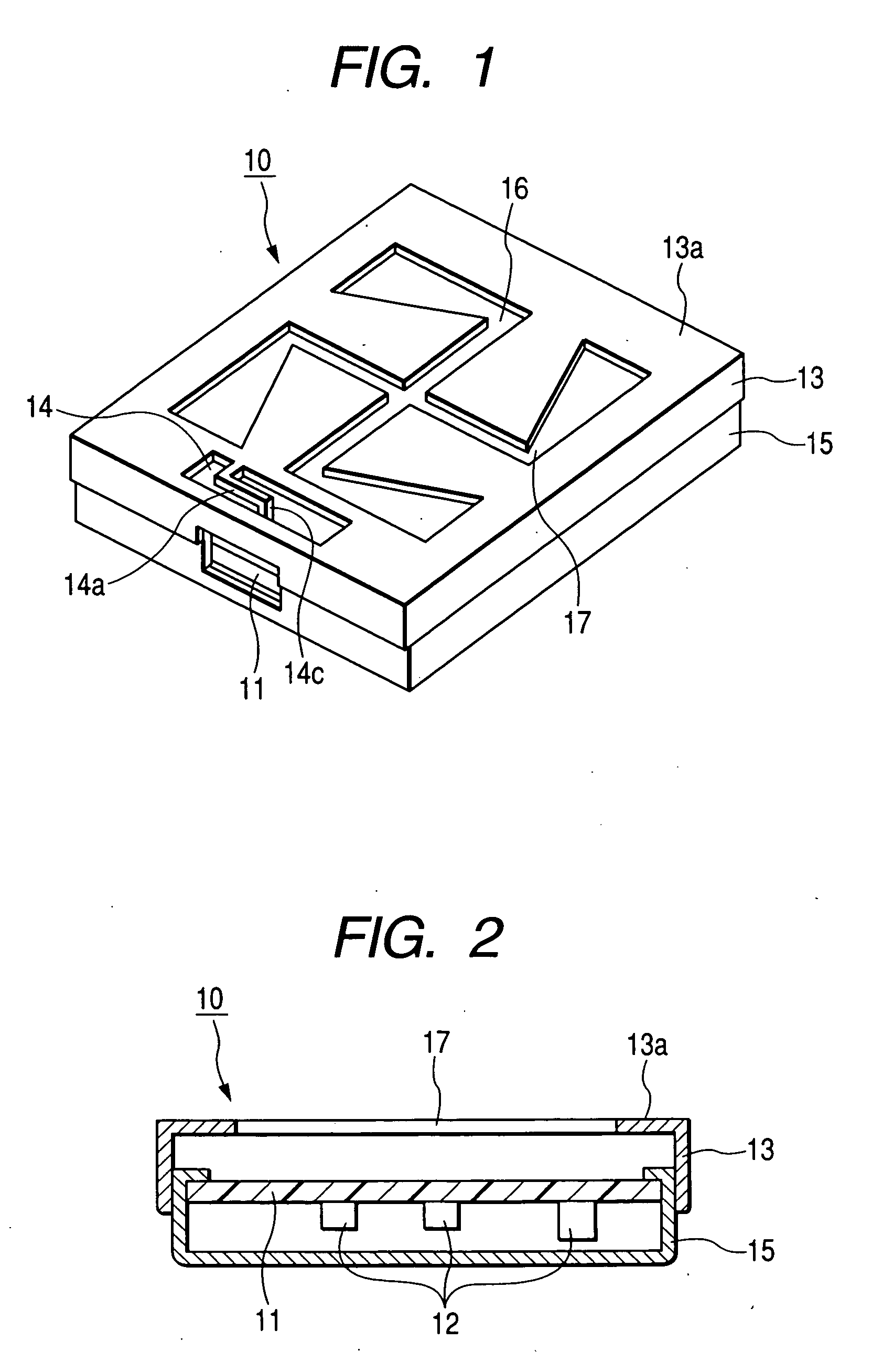
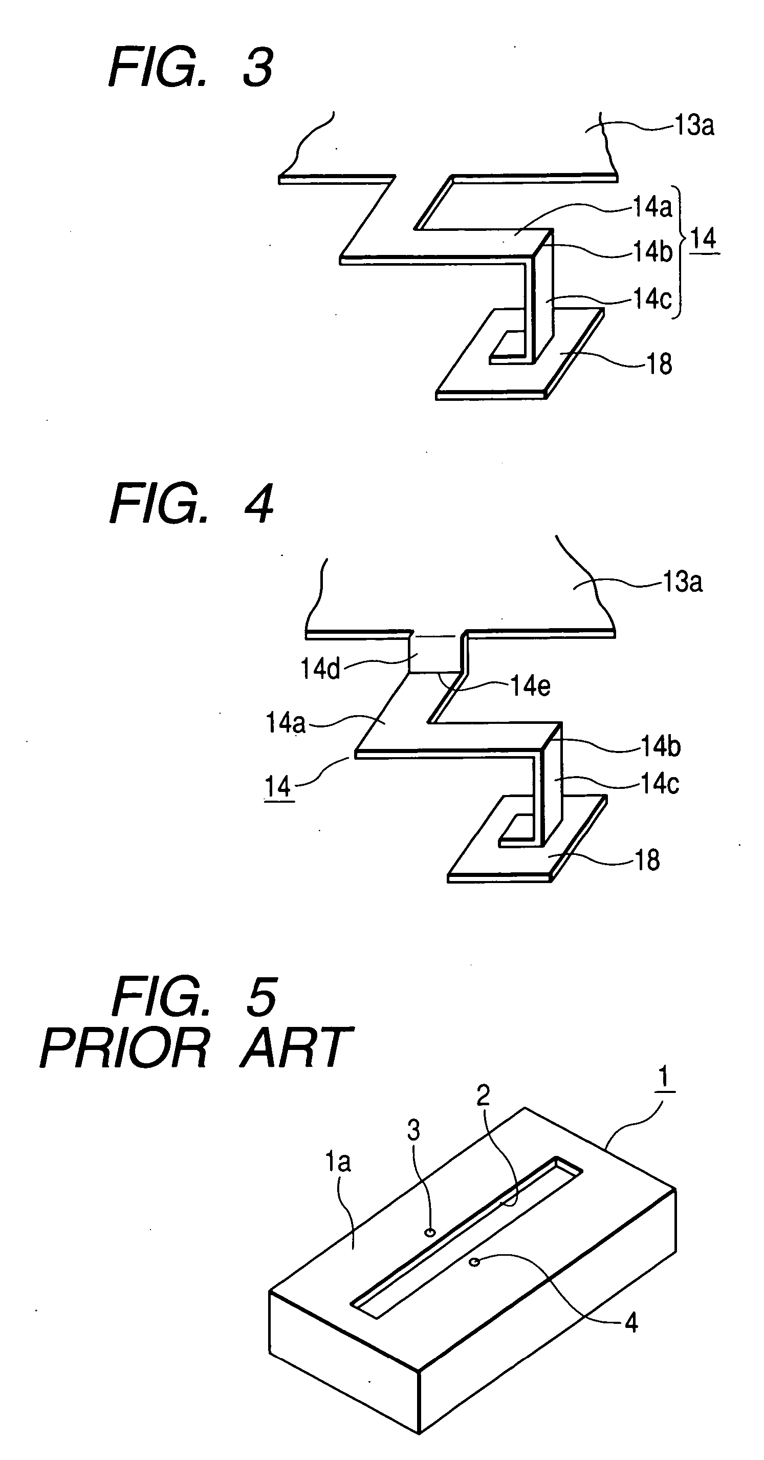
[0018] Hereinafter, an embodiment of the invention will be described with reference to the accompanying drawings. FIG. 1 is a perspective view of an antenna device according to the embodiment of the invention. FIG. 2 is a cross-sectional view of the antenna device according to the embodiment of the invention. FIG. 3 is a perspective view of essential parts showing a power feeding member of the antenna device according to the embodiment of the invention.

[0019] An antenna device 10 shown in FIGS. 1 and 2 mainly includes a circuit board 11, an electronic component 12, an upper shield case 13 made of a metal plate, a power feeding member 14, and a lower shield case 15 made of a metal plate. The circuit board 11 has high frequency circuits arranged thereon. The electronic component 12 is mounted on the circuit board 11. The upper shield case 13 covers an upper surface of the circuit board 11. The power feeding member 14 extending from the upper shield case 13 is a metal piece formed in ...


PUM


Abstract

An antenna device includes a circuit board, an upper shield case, a lower shield case, and a power feeding member. The circuit board has high frequency circuits arranged thereon. The upper shield case and the lower shield case cover the circuit board. The power feeding member extends from an upper plate of the upper shield case. Radiation slots and are formed in the upper plate. The power feeding member includes a horizontal portion, a bent portion, and a drooping portion, and a front end of the drooping portion is mounted on a land of the circuit board and soldered thereto. The horizontal portion protrudes from a base end which is continuous to the upper plate in a horizontal direction. The bent portion is formed by bending a front end of the horizontal portion at a right angle. The drooping portion extends downward from the bent portion.

Description

BACKGROUND OF THE INVENTION [0001] 1. Field of the Invention [0002] The present invention relates to an antenna device in which a slot antenna which excites a radiation slot formed in a metal plate and a circuit board having high frequency circuits connected to the slot antenna through a power feeding member are integrally formed, and more particularly, to a structure of the power feeding member. [0003] 2. Description of the Related Art [0004] In this type of an antenna device, power feeding is implemented by forming a radiation slot in a metal case which covers a circuit board, thus allowing the case to function as a slot antenna. Therefore, the antenna device is suitable for a vehicle because miniaturization and cost reduction can be easily achieved. [0005] FIG. 5 is a perspective view of a slot antenna according to the related art (for example, see JP-A-2003-218629 (page 2, FIG. 5). This slot antenna is constructed such that a radiation slot 2 is formed in an upper plate 1a of a ...

Claims


Application Information

Patent Timeline
Patent Type & Authority Applications(United States)
IPC IPC(8): H01Q13/10
CPCH01Q9/0457H01Q13/10
Inventor YUANZHU, DOU
Owner ALPS ALPINE CO LTD
Why Eureka
Try Eureka