Optical image stabilizer for camera lens assembly

Inactive Publication Date: 2006-04-13
SAMSUNG ELECTRONICS CO LTD
View PDF0 Cites 18 Cited by
  • Summary
  • Abstract
  • Description
  • Claims
  • Application Information

AI Technical Summary

Benefits of technology

[0014] Accordingly, the present invention has been made to solve the above-mentioned problems occurring in the prior art and provides a

Problems solved by technology

However, CCD sensors have disadvantages of high power consumption and complicated structures.
When photographing moving images using such image sensors, unstable images are captured due to the trembling of cameras resulting from external causes, such as the user's trembling hands and mounting of cameras on vehicles.
However, the conventional

Method used


Image

  • Optical image stabilizer for camera lens assembly
  • Optical image stabilizer for camera lens assembly
  • Optical image stabilizer for camera lens assembly

Examples


Embodiment Construction

[0024] Hereinafter, embodiments of the present invention will be described with reference to the accompanying drawings. For the purposes of clarity and simplicity, a detailed description of known functions and configurations incorporated herein will be omitted as it may make the subject matter of the present invention unclear.

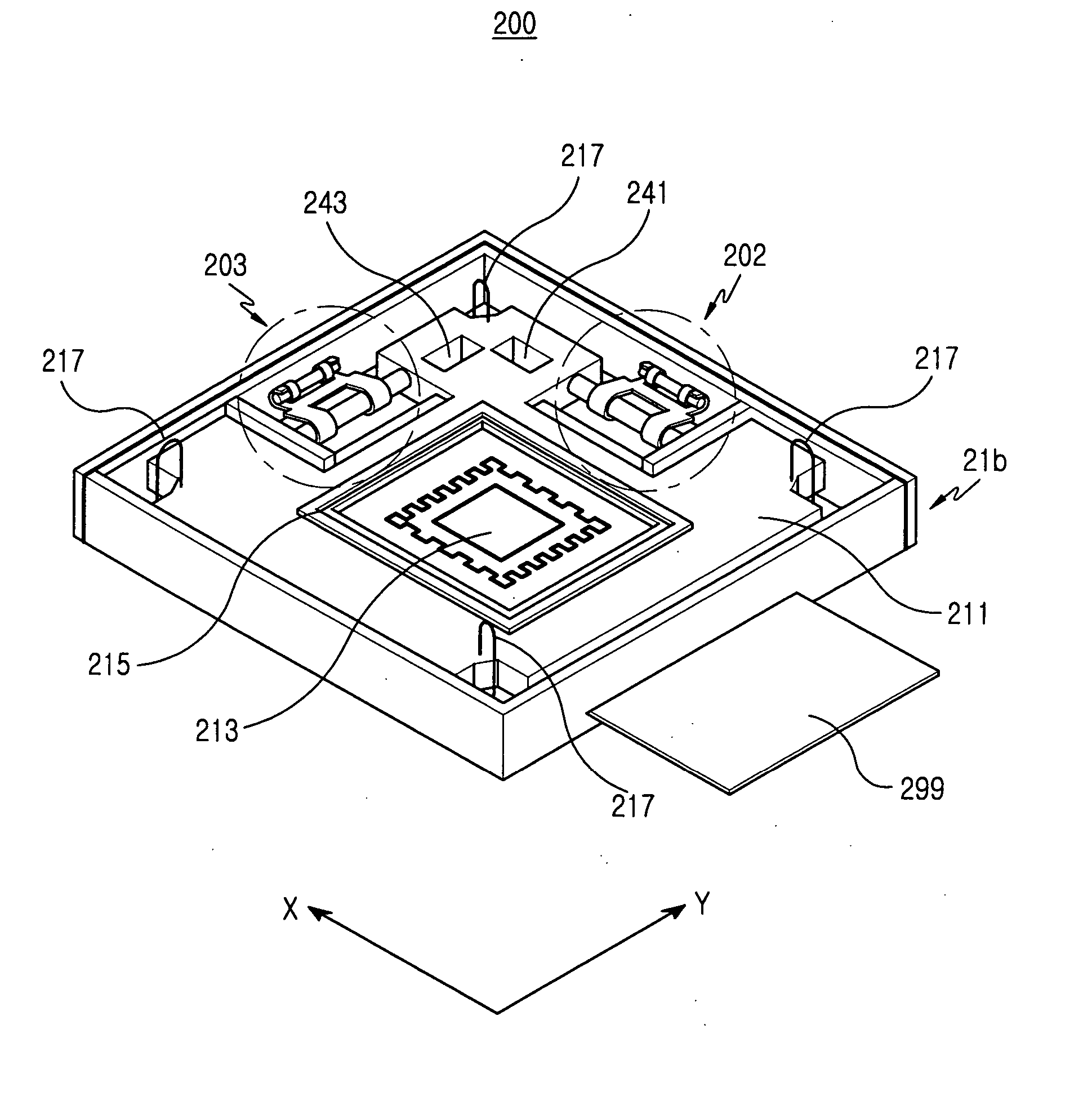
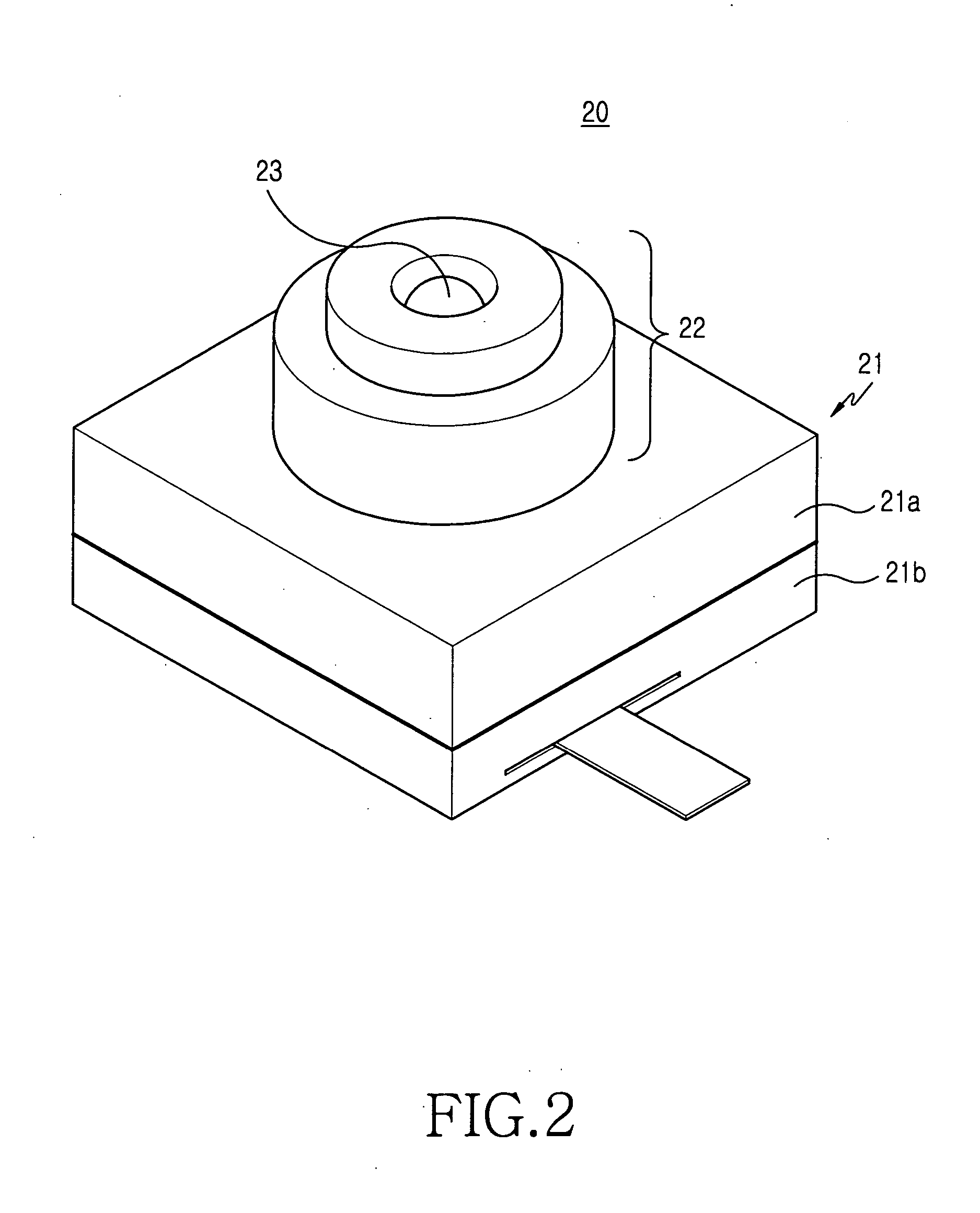
[0025] Referring to both FIGS. 2 and 3, the optical image stabilizer 200 of the camera lens assembly 20 is disposed in a housing 21. The optical image stabilizer 200 serves to correct the position of an image sensor 213 according to the trembling of user's hands. The camera lens assembly 20 has a housing 21 having an upper housing 21a and a lower housing 21b, and an optical tube 22 in which at least one lens (not shown) is contained. The optical tube 22 extends from the upper housing 21a and has an exposure window 23 on the terminal surface thereof. The optical image stabilizer 200 including the image sensor 213, etc., is contained in the housing 21.

[0026] Th...


PUM


Abstract

An optical image stabilizer for a camera lens assembly is disclosed, wherein the stabilizer includes a housing; a board disposed movably in the housing, the board and the housing being spaced apart from each other; an image sensor disposed on the board for transforming image information inputted thereto into electric signals; a plurality of wire frames for supporting the board, wherein both ends of each wire frame are coupled to the housing and the board, respectively; and a driving unit for correcting the position of the image sensor by moving the board according to degrees of trembling of user's hands. The driving unit on which an image sensor is mounted is present substantially on the same surface as the board itself, thereby allowing the downsize of a camera lens assembly.

Description

CLAIM OF PRIORITY [0001] This application claims priority to an application entitled “Optical Image Stabilizer for Camera Lens Assembly,” filed in the Korean Intellectual Property Office on Oct. 12, 2004 and assigned Serial No. 2004-81215, the contents of which are hereby incorporated by reference. BACKGROUND OF THE INVENTION [0002] 1. Field of the Invention [0003] The present invention relates to a camera device, and more particularly to an optical image stabilizer for a camera lens assembly. [0004] 2. Description of the Related Art [0005] As generally known in the art, there are two types of two-dimensional sensors, namely a CCD (Chare Coupled Device) sensor and a CMOS (Complementary Metal Oxide Semiconductor) sensor. These sensors are used for photographing dynamic and static images. CCD sensors provide excellent characteristics compared to CMOS sensors in terms of image quality. However, CCD sensors have disadvantages of high power consumption and complicated structures. Thus, C...

Claims


Application Information

Patent Timeline
IPC IPC(8): H04N5/228G03B5/00G03B30/00H04N5/232H04N5/335H04N5/351H04N5/372H04N5/374
CPCH04N5/2253H04N5/23248H04N5/23287H04N23/54H04N23/68H04N23/687H04N23/60
Inventor PYO, SUN-HYOUNGSHIN, DOO-SIK
Owner SAMSUNG ELECTRONICS CO LTD
Why Eureka
Try Eureka