Image processor, method for informing status change of image processor and computer program product

Active Publication Date: 2006-04-13
KONICA MINOLTA BUSINESS TECH INC
View PDF17 Cites 12 Cited by
  • Summary
  • Abstract
  • Description
  • Claims
  • Application Information

AI Technical Summary

Benefits of technology

[0019] According to the present invention, when a change such as addition of a new function

Problems solved by technology

Then, an error message is sent to the devices.
Then, if the abnormal operation has not resolved yet, error information is sent to a host computer that sent the print data that was being processed at the time when the abnormal operation was detected or a host computer that sent print data before or after the time.
However, according to the conventional method as described in each of the above-mentioned patent publication, it is difficult to introduce efficiently a newly added function of the image processor to users who use the im

Method used


Image

  • Image processor, method for informing status change of image processor and computer program product
  • Image processor, method for informing status change of image processor and computer program product
  • Image processor, method for informing status change of image processor and computer program product

Examples


Embodiment Construction

[0034] Hereinafter, the present invention will be explained more in detail with reference to embodiments and drawings.

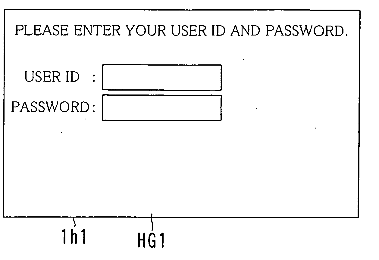
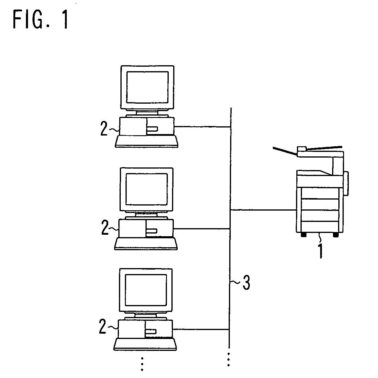
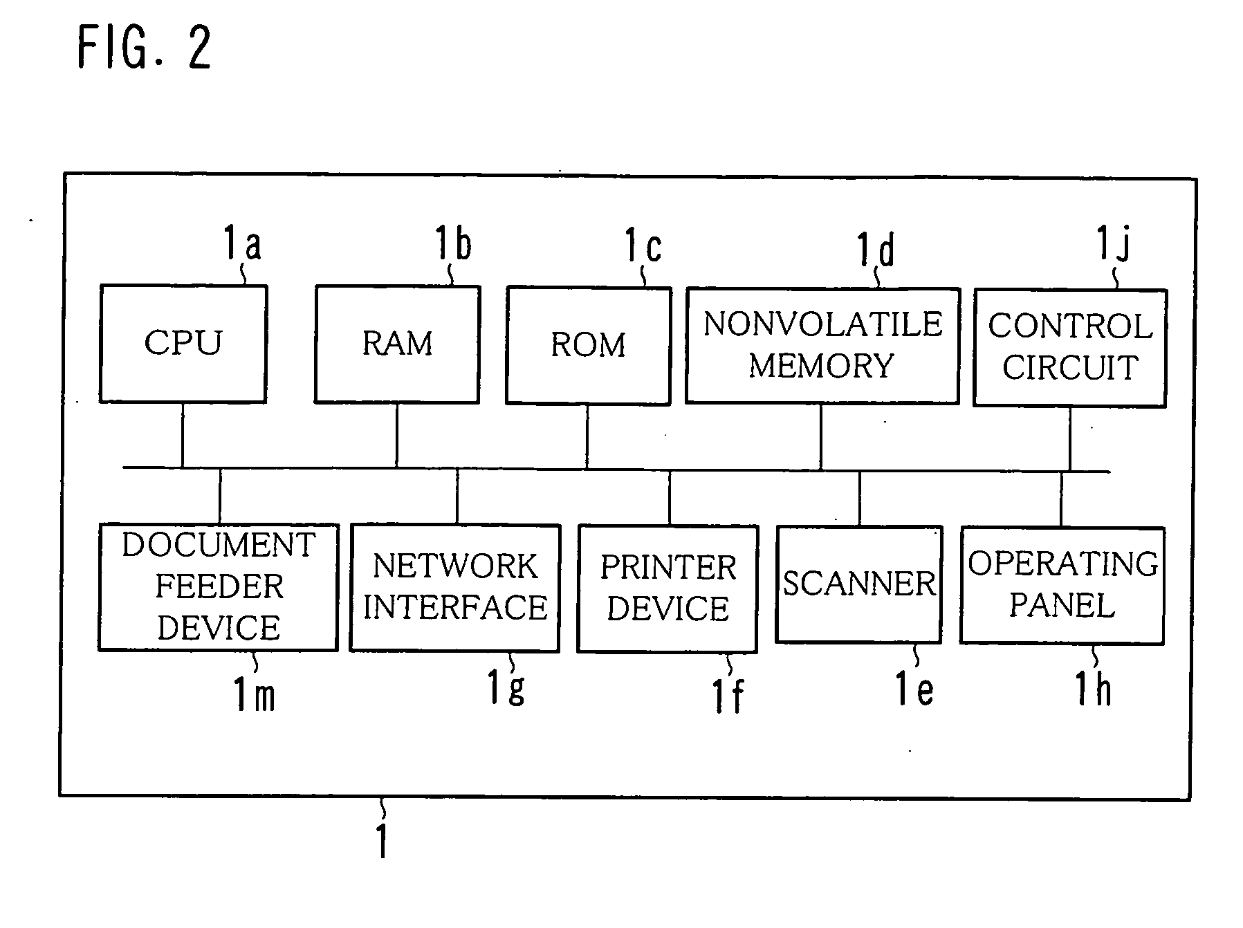
[0035]FIG. 1 shows an example of an overall structure of a network system equipped with an image forming device 1 according to the present invention, FIG. 2 shows an example of a hardware structure of the image forming device 1, FIG. 3 shows an example of a structure of an operating panel 1h, FIG. 4 shows an example of a functional structure of the image forming device 1.

[0036] The image forming device 1 according to the present invention is connected to a terminal device 2 via a communication line 3 as shown in FIG. 1. As the communication line 3, a LAN, the Internet, a public telephone line or a private line can be used. As a protocol, FTP (File Transfer Protocol), POP (Post Office Protocol) or SMTP (Simple Mail Transfer Protocol) can be used.

[0037] The image forming device 1 is a device including integrated functions of a copy, network printing, a scanner or th...


PUM


Abstract

An image forming device includes a user job history database for storing execution condition information that indicates an execution condition of the job in relationship with user identification information for distinguishing a user who made the instruction for each executed job, a device structure detection portion for detecting a change in a state of the image processor, a notification target determination portion for determining a notification target user who is a user to be notified of the change in accordance with the execution condition information and the user identification information stored in the user job history database, and a new function notification portion for notifying the change to the determined notification target user.

Description

[0001] This application is based on Japanese Patent Application No. 2004-295446 filed on Oct. 7, 2004, the contents of which are hereby incorporated by reference. BACKGROUND OF THE INVENTION [0002] 1. Field of the Invention [0003] The present invention relates to an image processor such as multifunction peripherals that can send data to a terminal device of a user via a network and a method for controlling the image processor. [0004] 2. Description of the Prior Art [0005] Recently, an image processor such as a printer or a copying machine is equipped with various functions. For example, an image processor is proposed that has a scanner function, a FAX function, or a document server (box) function adding to a conventional copy function and a network printing function. Such an image processor is called a multifunction device or multifunction peripherals (MFP). [0006] Some image processors have all the above-mentioned functions as standard functions, while other image processors suppor...

Claims


Application Information

Patent Timeline
IPC IPC(8): G06F3/12
CPCH04N1/00007H04N1/00037H04N1/00079H04N1/00204H04N2201/0039H04N2201/0094
Inventor NAKATA, HIRONOBUMURAKAMI, MASAKAZUSAWAYANAGI, KAZUMIKOBAYASHI, MINAKO
Owner KONICA MINOLTA BUSINESS TECH INC
Why Eureka
Try Eureka