Hybrid light modulator

Inactive Publication Date: 2006-04-13
SAMSUNG ELECTRO MECHANICS CO LTD
View PDF5 Cites 2 Cited by
  • Summary
  • Abstract
  • Description
  • Claims
  • Application Information

AI Technical Summary

Benefits of technology

[0017] Accordingly, the present invention has been made keeping in mind the above problems occurring in the prior art, and an object of the present invention is to provide a hybrid light modulator which includes ribbons having uneven upper surfaces, so that incident light is diffracted by the uneven upper surfaces of the ribbons from an early light receiving stage, but not by controlling the height difference between moving ribbons, thus realizing miniaturization and high integration of the hybrid light modulator.

Problems solved by technology

However, the Bloom light modulator adopts an electrostatic method to control a position of the micromirror, which has disadvantages in that an operating voltage is relatively high (usually, 20 V or so) and a correlation between the applied voltage and displacement is not linear, resulting in poor reliability in the course of controlling light.
However, the conventional light modulators disclosed in the patent filed by Bloom et al. have reached the limit in miniaturization.

Method used


Image

  • Hybrid light modulator
  • Hybrid light modulator
  • Hybrid light modulator

Examples


first embodiment

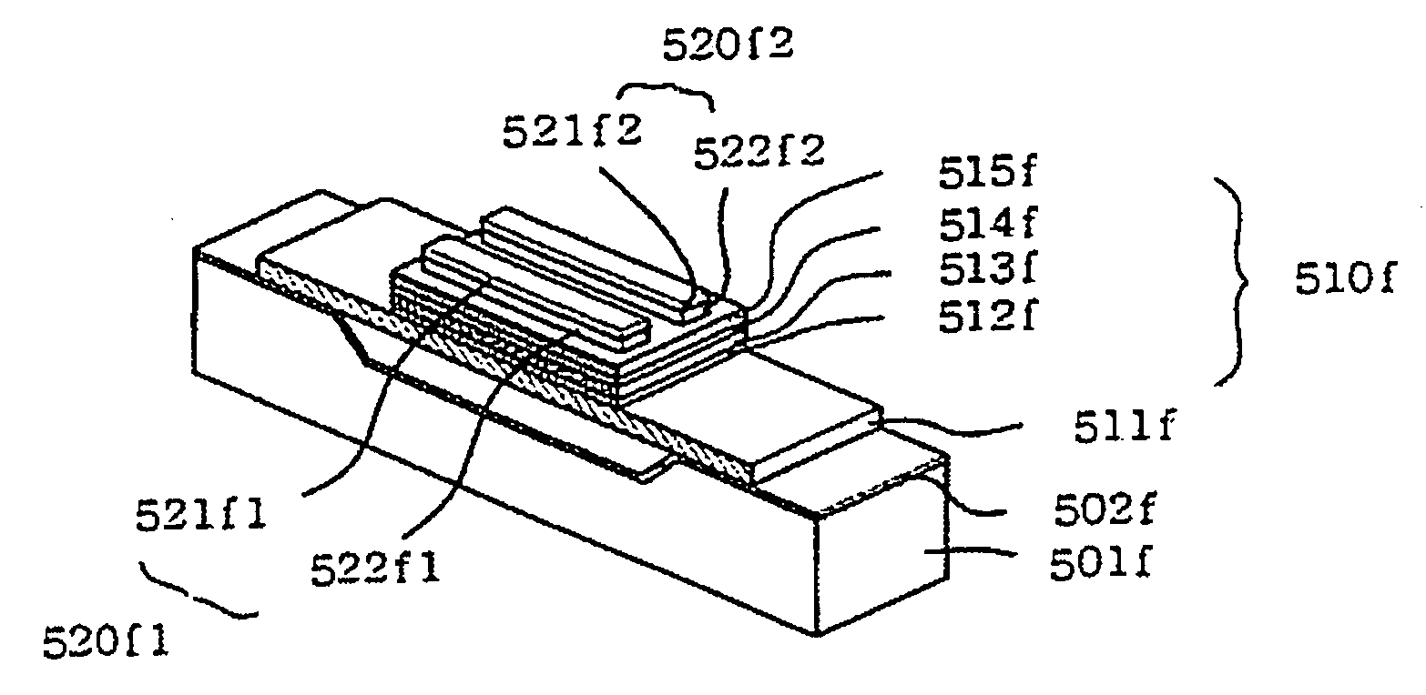
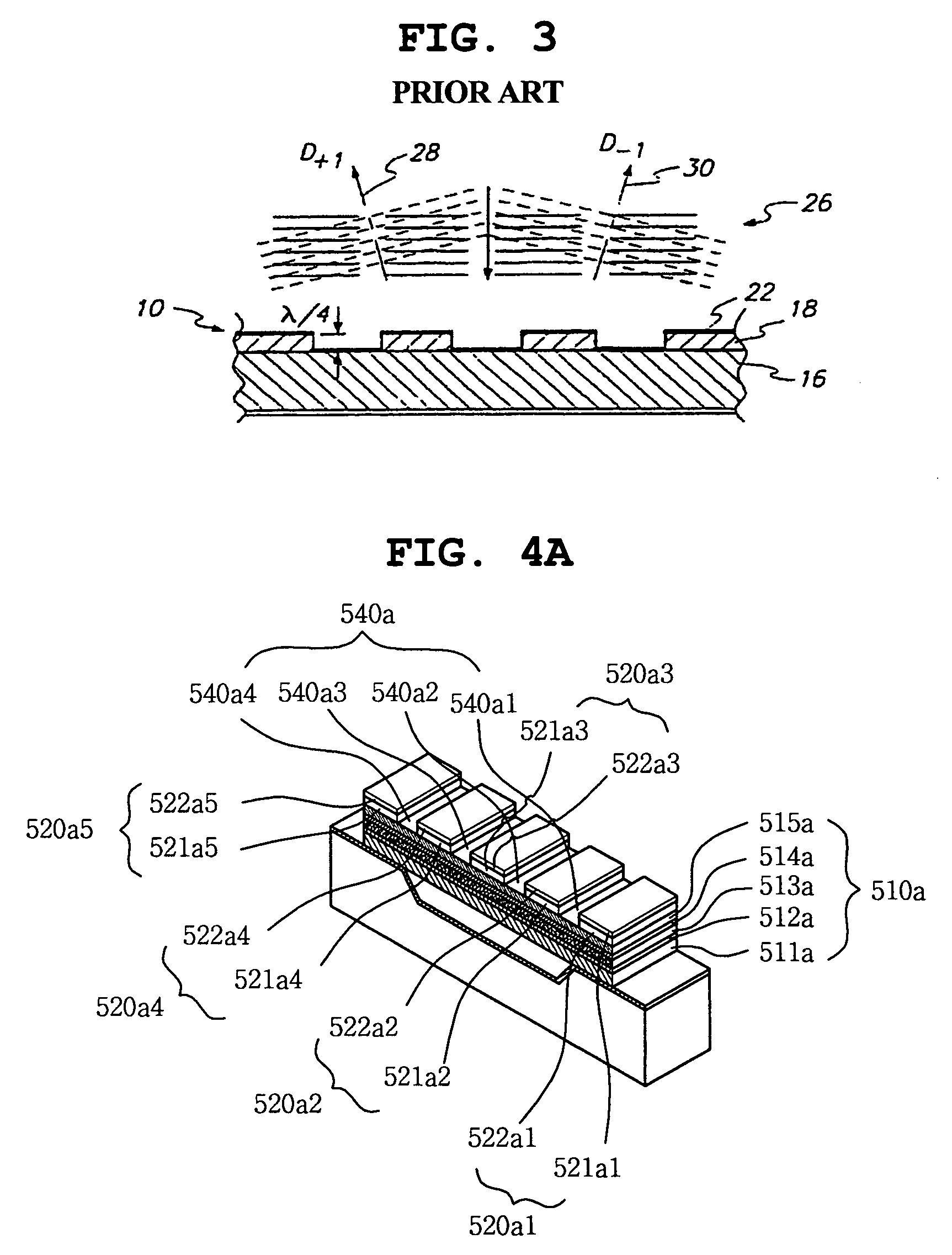
[0037]FIG. 4a is a perspective view showing an element 510a of a recess-type hybrid thin-film piezoelectric light modulator, according to the present invention. Referring to FIG. 4a, the element 510a includes a plurality of protrusions 520a1, 520a2, 520a3, 520a4 and 520a5 which are disposed on a micromirror layer 515a of the element 510a to reflect and diffract incident light. Each of the protrusions 520a1, 520a2, 520a3, 520a4 and 520a5 has a rectangular column shape (ribbon shape). However, the protrusions can be of other shapes, such as square or oval. The protrusions 520a1, 520a2, 520a3, 520a4 and 520a5 are arranged along a longitudinal axis of the element 510a, passing over the recess, to be spaced apart from each other at regular intervals (for example, each interval is the same as the width of the protrusion 520a1, 520a2, 520a3, 520a4, 520a5). Each protrusion 520a1, 520a2, 520a3, 520a4, 520a5 includes a support layer 521a1, 521a2, 521a3, 521a4, 521a5 which is attached at a low...

second embodiment

[0047]FIG. 4b is a perspective view showing an element 510b of a recess-type hybrid thin-film piezoelectric light modulator, according to the present invention. Referring to FIG. 4b, the element 510b includes a plurality of protrusions 520b1, 520b2 and 520b3 which is placed on a micromirror layer 515b of the element 510b that reflects and diffracts incident light. Each protrusion 520b1, 520b2, 520b3 has a rectangular column shape (ribbon shape). When the longitudinal axis of the element 510b is defined as the axis passing over the recess, the protrusions 520b1, 520b2 and 520b3 are arranged along a latitudinal axis of the element 510b, unlike the element 510a of FIG. 4a. The protrusions 520b1, 520b2 and 520b3 are spaced apart from each other at regular intervals (for example, each interval is the same as the width of the protrusion 520b1, 520b2, 520b3). Each protrusion 520b1, 520b2, 520b3 includes a support layer 521b1, 521b2, 521b3 which is attached at a lower surface thereof to an ...

third embodiment

[0049]FIG. 4c is a perspective view showing an element 510c of a recess-type hybrid thin-film piezoelectric light modulator, according to the present invention. Referring to FIG. 4c, the element 510c includes a plurality of protrusions 520c1, 520c2 and 520c3 which is placed on a micromirror layer 515c of the element 510c that reflects and diffracts incident light. Each protrusion 520c1, 520c2, 520c3 has a rectangular column shape (ribbon shape). The protrusions 520c1, 520c2 and 520c3 are arranged along a longitudinal axis of the element 510c, passing over the recess, to be spaced apart from each other at regular intervals (for example, each interval is the same as the width of the protrusion 520c1, 520c2, 520c3). Each protrusion 520c1, 520c2, 520c3 includes a support layer 521c1, 521c2, 521c3 which is attached at a lower surface thereof to an upper surface of the micromirror layer 515c of the element 510c. The protrusion 520c1, 520c2, 520c3 further includes a mirror layer 522c1, 522...


PUM


Abstract

The present invention provides a hybrid light modulator. The hybrid light modulator of the present invention includes an element having a protrusion to diffract incident light even at an early light receiving stage and to control the diffractive angle of the light using a microactuator, unlike conventional diffractive light modulators which reflect and diffract incident light using a plurality of micromirror actuators. Therefore, the present invention realizes device miniaturization and assures easy digital operation. Furthermore, piezoelectric force may be used to provide an actuating force to the element of the hybrid light modulator. Alternatively, electrostatic or electromagnetic force may be used as an actuating force for the hybrid light modulator.

Description

BACKGROUND OF THE INVENTION [0001] 1. Field of the Invention [0002] The present invention relates generally to light modulators, and more particularly, to a hybrid light modulator which includes a plurality of ribbons each having a plurality of protrusions to diffract incident light from an early light receiving stage and to control a diffractive angle of the light beam using a microactuator, thereby realizing the miniaturization of a device and assuring the ease of digital operation, unlike conventional diffractive optical modulators in which incident light is reflected and diffracted by the operation of a plurality of micromirror actuators. [0003] 2. Description of the Related Art [0004] Generally, an optical signal processing technology has advantages in that a great amount of data is quickly processed in a parallel manner unlike a conventional digital information processing technology in which it is impossible to process a great amount of data in real time, and studies have been...

Claims


Application Information

Patent Timeline
IPC IPC(8): G02B26/00
CPCG02B26/0808
Inventor YUN, SANG KYEONG
Owner SAMSUNG ELECTRO MECHANICS CO LTD
Why Eureka
Try Eureka