Luminescent solar concentrator devices

Inactive Publication Date: 2009-05-14
GOROG ISTVAN +1
View PDF3 Cites 24 Cited by
  • Summary
  • Abstract
  • Description
  • Claims
  • Application Information

AI Technical Summary

Benefits of technology

[0009]A relatively large field of laminated fluorescent square LSC tiles are interdigitated by long thin bi-facial silicon photovoltaic cells. The laminated fluorescent LSC tiles each comprise a thick clear substrate bonded to a fluorescent dye film with a mirror backing and a protective layer. Incident sunlight is received by the clear substrate's face, and the dye converts that to fluorescent light. The resulting fluorescent light can only escape out the pe

Problems solved by technology

Fossil fuels as a principal energy source have a number of problems.
They are not renewable, and the day will come when supplies dwindle below demand levels.
Fossil fuels also contribute to air, land, and water pollution, and expensive and extraordinary measures are needed to control and limit such pollution.
But such technology is also expensive.
Even though the capital costs are high, the operational costs are very low.
There are two significant cost drivers in LSC devices, the costs associated with the fluorescent-dye light conversion, and the costs associated with the silicon photovoltaic conversion.

Method used


Image

  • Luminescent solar concentrator devices
  • Luminescent solar concentrator devices
  • Luminescent solar concentrator devices

Examples


Embodiment Construction

[0017]In the following detailed description of the preferred embodiments, reference is made to the accompanying drawings, which form a part hereof, and within which are shown by way of illustration specific embodiments by which the invention may be practiced. It is to be understood that other embodiments may be utilized and structural changes may be made without departing from the scope of the invention.

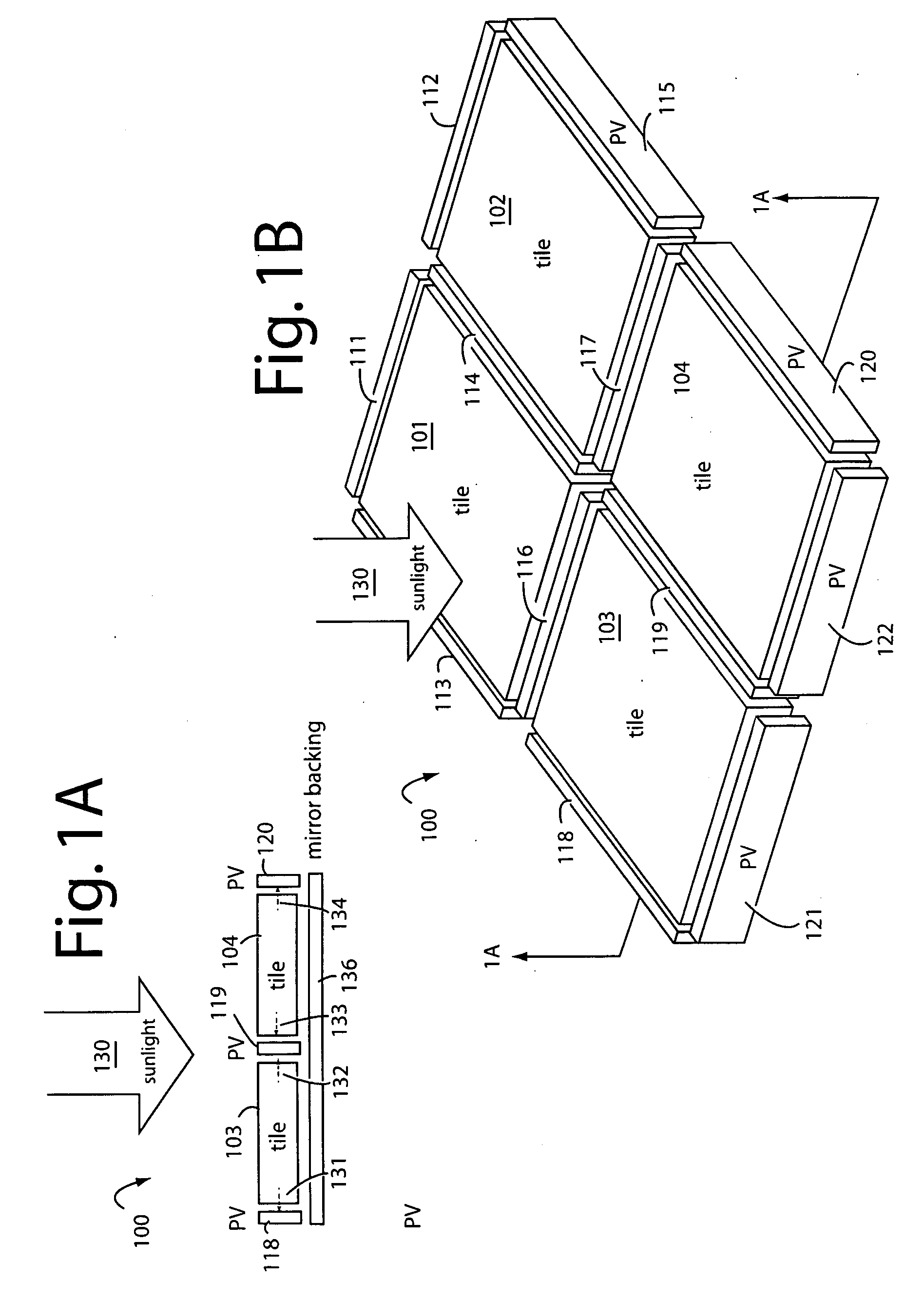
[0018]FIGS. 1A and 1B show a luminescent solar concentrator (LSC) photovoltaic (PV) device embodiment of the present invention, that is referred to herein by the general reference numeral 100. Device 100 is fabricated with a number of LSC tiles 101-104 interdigitated and surrounded with thin, long, bi-facial PV cells 111-120. For example, one type of suitable PV cell is commonly called a SLIVER. The several LSC tiles 101-104 are made of an optically clear substrate material like glass or polycarbonate, and either doped with fluorescent dye or bonded to a fluorescent dye film backing....


PUM


Abstract

A relatively large field of laminated fluorescent square LSC tiles are interdigitated by long thin bi-facial silicon photovoltaic cells. The laminated fluorescent LSC tiles each comprise a thick clear substrate bonded to a fluorescent dye film with a mirror backing and a protective layer. Incident sunlight is received by the clear substrate's face, and the dye converts that to fluorescent light. The resulting fluorescent light can only escape out the perimeter edges of the clear substrate where the photovoltaic cells are positioned. Each silicon photovoltaic cell receives fluorescent light laterally from the adjacent and opposite edges of the two fluorescent LSC tiles it separates. The collection area of the face of each fluorescent LSC tile is very large compared to the areas of the edges, and so highly concentrated light is provided to relatively small area photovoltaic cells for conversion to electricity.

Description

RELATED APPLICATIONS[0001]This Application claims benefit of U.S. Provisional Patent Application, Ser. 61 / 002,439, filed Nov. 6, 2007, and titled, IMPROVED LSC PHOTOVOLTAIC DEVICES.FIELD OF THE PRESENT INVENTION[0002]The present invention relates to luminescent solar concentrator photovoltaic cells, and in particular to methods for and devices with reduced silicon areas and reduced fluorescent dye usage.BACKGROUND[0003]Fossil fuels as a principal energy source have a number of problems. They are not renewable, and the day will come when supplies dwindle below demand levels. Fossil fuels also contribute to air, land, and water pollution, and expensive and extraordinary measures are needed to control and limit such pollution. Cleaner, renewable energy sources are widely seen as the only long term solutions. Today, they are replacing fossil fuels in ever expanding ways.[0004]The use of fossil fuels to produce electricity can be reduced with solar energy systems. Semiconductor photovolt...

Claims


Application Information

Patent Timeline
IPC IPC(8): H01L31/042
CPCH01L31/055H01L31/0547Y02E10/52
Inventor GOROG, ISTVANPRESSLEY, ROBERT J.
Owner GOROG ISTVAN
Why Eureka
Try Eureka