First surface mirror with chromium nitride layer

a chromium nitride and mirror technology, applied in the direction of mirrors, mountings, instruments, etc., can solve the problems of poor reflection, glass/cr structure suffer from pinhole related problems, mirror structure is susceptible to pinhole formation in the metallic cr layer, etc., to improve the durability of the mirror

a chromium nitride and mirror technology, applied in the direction of mirrors, mountings, instruments, etc., can solve the problems of poor reflection, glass/cr structure suffer from pinhole related problems, mirror structure is susceptible to pinhole formation in the metallic cr layer, etc., to improve the durability of the mirror

US20060077580A1Inactive Publication Date: 2006-04-13GUARDIAN EURO S A R L +1

Image

  • First surface mirror with chromium nitride layer
  • First surface mirror with chromium nitride layer
  • First surface mirror with chromium nitride layer

Examples


examples

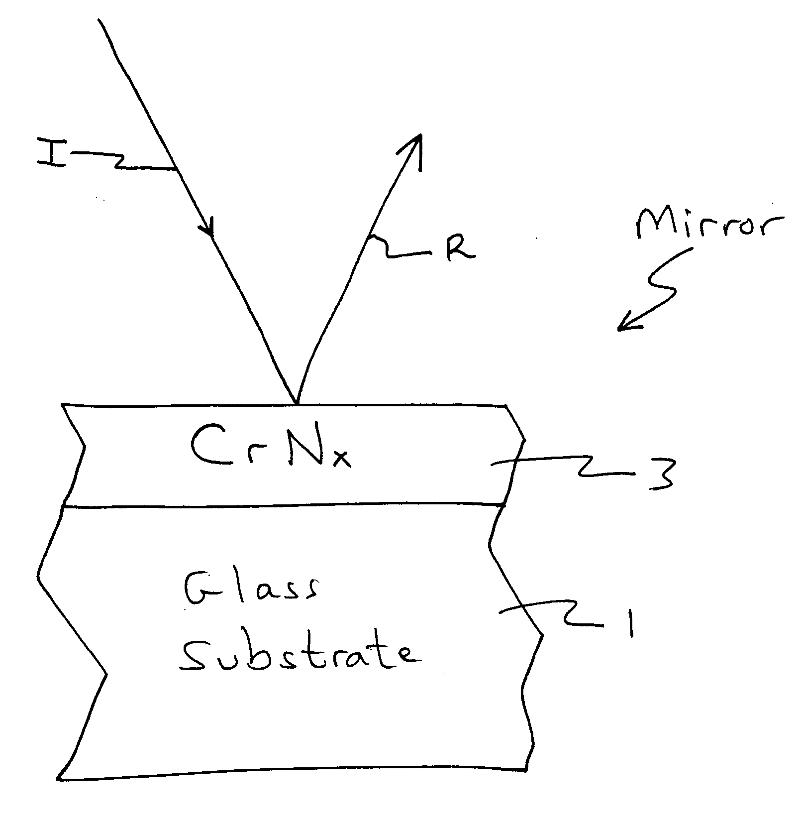
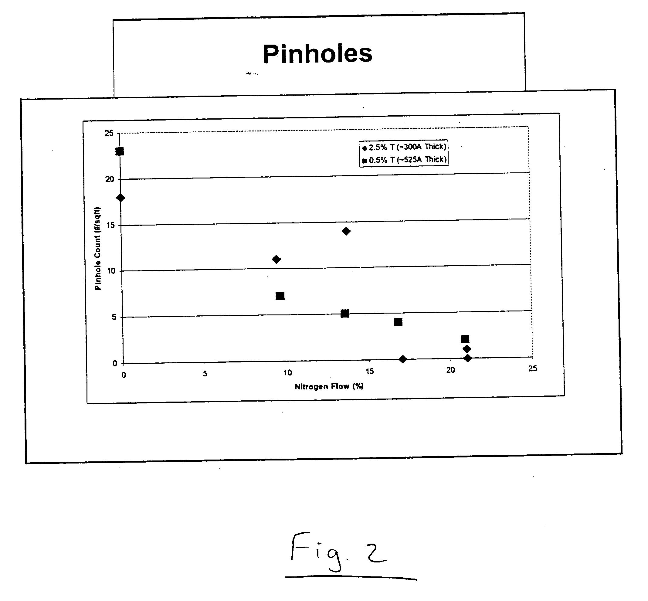
[0035] The following example first surface mirrors were made and tested, but are not intended to be limiting. Example 1 had a layer stack of glass / Cr, whereas the other examples all had a layer stack of glass / CrNx as shown in FIG. 1. The glass substrate 1 was about 2.3 mm thick. The examples were made by sputtering the Cr inclusive layer on the substrate using a Cr sputtering target in a gas atmosphere, using the following process parameters. Lower linespeeds were used for thicker layers and thus less visible transmission if desired.

Ex. 1Ex. 2Ex. 3Ex. 4Ex. 5Ex. 6Ex. 7N2 gas flow (sccm):09213113116019894Ar gas flow (sccm):970878825825790747878Total gas (sccm):970970956956950945972% N gas flow:09%14%14%17%21%10%Linespeed (ipm):1601601421501428590pressure (mTorr):2.62.52.42.42.32.22.5

[0036] It was found that the mirrors of Examples 2-6 (which included nitrogen in the Cr inclusive layer 3) had much fewer pinholes than did the mirror of Example 1 (which had a metallic Cr layer 3—thus, ...


PUM

PropertyMeasurementUnit
thickaaaaaaaaaa
thickaaaaaaaaaa
thickaaaaaaaaaa

Abstract

A mirror (e.g., first surface mirror) is provided with a layer of or including chromium nitride (CrNx). In certain example embodiments, the CrNx layer may be the primary reflective layer of the mirror. Surprisingly and unexpectedly, it has been found the addition of nitrogen to the chromium to form CrNx reduces pinhole formations in the resulting layer. In certain example embodiments, the more nitrogen which is introduced into the layer, the smaller the number and / or size of pinholes in the Cr inclusive layer. In certain example embodiments, it has also been found that the addition of nitrogen to Cr may improve durability.

Description

[0001] This application is related to a first-surface mirror including a layer of or including chromium nitride (CrNx). In certain example embodiments, a reflective layer of the mirror comprises chromium nitride, and is nitrided to an extent so as to reduce undesirable pinhole formation and / or improve adhesion. In certain example non-limiting instances, such first surface mirrors may be used in the context of a projection television (PTV) apparatus, automotive mirrors, or in any other suitable application. BACKGROUND OF THE INVENTION [0002] Mirrors for various uses are known in the art. For example, see U.S. Pat. Nos. 5,923,464 and 4,309,075 (all hereby incorporated herein by reference). Mirrors are also known for use in projection televisions and other suitable applications. In the projection television context, see for example U.S. Pat. Nos. 6,275,272, 5,669,681 and 5,896,236 (all hereby incorporated herein by reference). [0003] One type of mirror is a second or back surface mirro...

Claims


Application Information

Patent Timeline
13 Apr 2006
Publication
US20060077580A1
IPC
G02B5/08
CPC
G02B5/08
Inventors
WUILLAUME, FRANCIS; DIETRICH, ANTON