Resistor having a predetermined temperature coefficient

a technology of resistor and temperature coefficient, which is applied in the field of resistors, can solve the problems of adversely affecting the output voltage signal of resistor dividers or wheatstone bridges

Active Publication Date: 2006-04-13
ALLEGRO MICROSYSTEMS INC
View PDF93 Cites 59 Cited by
  • Summary
  • Abstract
  • Description
  • Claims
  • Application Information

AI Technical Summary

Problems solved by technology

It will be recognized that the temperature coefficient of the magnetoresistance element, when used in a resistor divider or in a Wheatstone bridge arrangement, can adversely affect the expected output voltage signal of the resistor divider or the Wheatstone bridge.

Method used


Image

  • Resistor having a predetermined temperature coefficient
  • Resistor having a predetermined temperature coefficient
  • Resistor having a predetermined temperature coefficient

Examples


Embodiment Construction

[0023] Before describing the resistor of the present invention, some introductory concepts and terminology are explained. As used herein, the term “disposed over” is used to refer to a relative placement, without suggesting a requirement for up or down orientation. For example, a first layer in combination with a second layer disposed over the first layer is not meant to require that the second layer be above the first layer. Merely by flipping the above-described combination, it can be seen that the second layer can be either above or below the first layer. The term “disposed over” also does not suggest a requirement for physical contact. For example, the above-described first and second layers need not be touching.

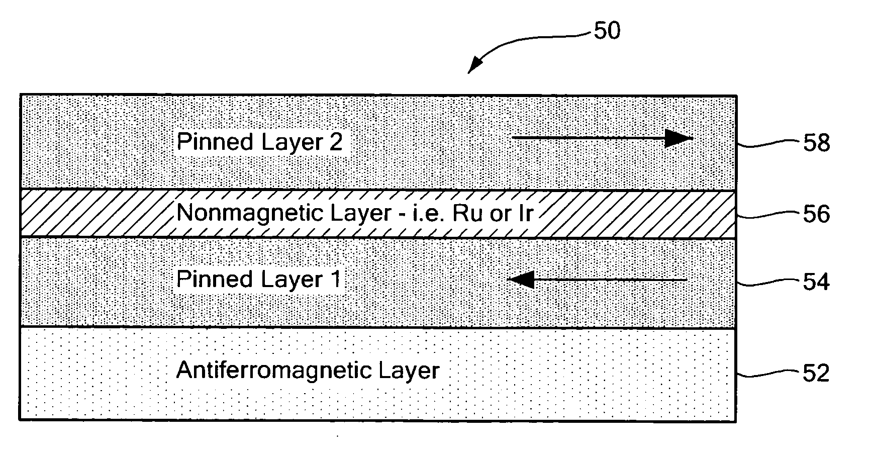
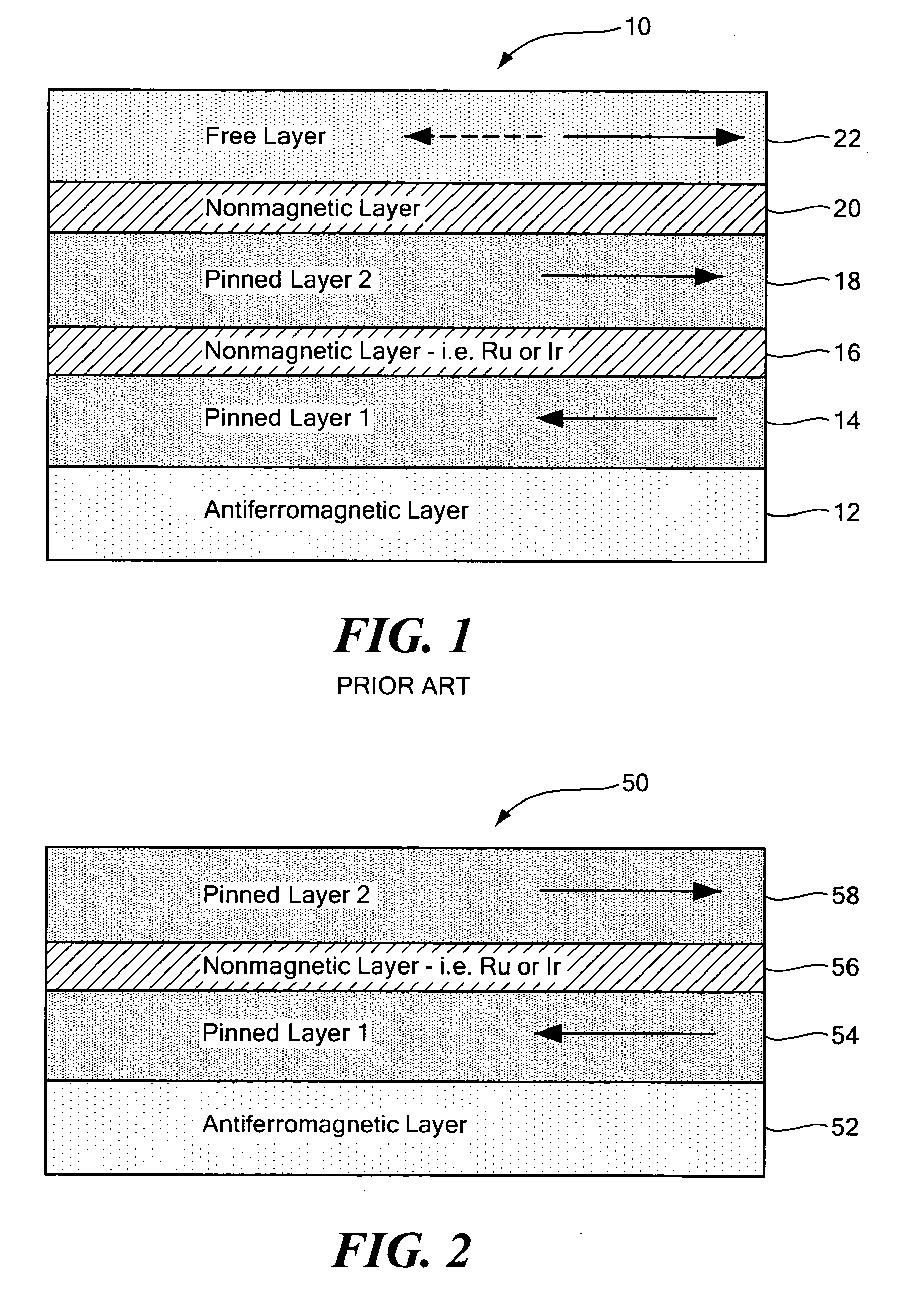
[0024] Referring to FIG. 2, an exemplary resistor 50 having a predetermined temperature coefficient is provided as a material stack including an antiferromagnetic layer 52, a first pinned layer 54, a non-magnetic layer 56, and a second pinned layer 58. The antiferromagn...


PUM

PropertyMeasurementUnit
magnetic fieldaaaaaaaaaa
antiferromagneticaaaaaaaaaa
electrical resistanceaaaaaaaaaa

Abstract

A material stack has an electrical resistance generally the same in the presence of a magnetic field and in the presence of no magnetic field. The electrical resistance of the material stack has a temperature coefficient generally the same as a magnetoresistance element.

Description

CROSS REFERENCE TO RELATED APPLICATIONS [0001] Not Applicable. STATEMENT REGARDING FEDERALLY SPONSORED RESEARCH [0002] Not Applicable. FIELD OF THE INVENTION [0003] This invention relates generally to electrical resistors and, in particular, to an electrical resistor having a predetermined temperature coefficient selected in accordance with a temperature coefficient of a magnetoresistance element. BACKGROUND OF THE INVENTION [0004] Magnetoresistance elements are known to be manufactured in a variety of configurations, including, but not limited to giant magnetoresistance (GMR) elements, and anisotropic magnetoresistance (AMR) elements. [0005] Referring to FIG. 1, a prior art GMR element 10 is formed having a plurality of layers, including an antiferromagnetic layer 12, a first pinned layer 14, a first non-magnetic layer 16, a second pinned layer 18, a second non-magnetic layer 20, and a free layer 22. In one conventional GMR element, the antiferromagnetic layer 12 comprises PtMn, th...

Claims


Application Information

Patent Timeline
Patent Type & Authority Applications(United States)
IPC IPC(8): G11B5/33G11B5/127G01R33/02H01L43/10H01L43/08H01L43/06H01L43/04H01L43/02H01L43/00
CPCB82Y25/00G01R33/093H01L27/22H01C7/06H01F10/3272H01C7/006G01R15/205H10B61/00H10N59/00
Inventor TAYLOR, WILLIAM P.DOOGUE, MICHAEL C.
Owner ALLEGRO MICROSYSTEMS INC
Why Eureka
Try Eureka