
Display element and mechanical mounting interface used therein

a technology of mechanical mounting and display element, which is applied in the direction of television system, identification means, instruments, etc., can solve the problems of not always designing large-scale displays, requiring the laborious removal of a large number of fasteners, and not providing a means of easily replacing worn emissive lighting modules, etc., to achieve the effect of reducing manufacturing and parts costs in large-scale display production

Inactive Publication Date: 2006-04-13
BARCO NV
View PDF7 Cites 21 Cited by
  • Summary
  • Abstract
  • Description
  • Claims
  • Application Information

AI Technical Summary

Benefits of technology

[0008] It is therefore an object of this invention to minimize manufacturing and parts costs in large-scale display production.
[0009] It is another object of this invention to provide lighting modules that can be quickly fastened or removed.
[0012] In particular, the present invention relates to an interchangeable mounting mechanism for quickly installing, maintaining, and disassembling LED, OLED or other emissive modular large-scale display.

Problems solved by technology

However, the market is now demanding cheaper and larger displays that have the flexibility to customize display sizes and colors, that have image and video capability, and that are easy to install, maintain, and disassemble, especially for use in temporary venues; these are market specifications that are not possible with the older technologies.
However, these large-scale displays are not always designed from the standpoint of easy and prompt installation or maintenance and, at best, ready access is often considered late in the execution of the design.
Replacing worn emissive lighting modules, for example, often requires the laborious removal of a generous number of fasteners, such as screws, nuts, bolts, clips, or the like.
However, the '669 patent fails to provide a means of easily replacing worn emissive lighting modules.
This can be problematic for companies that are constantly updating their hardware in an attempt to stay competitive in today's market place.

Method used


Image

  • Display element and mechanical mounting interface used therein
  • Display element and mechanical mounting interface used therein
  • Display element and mechanical mounting interface used therein

Examples


Embodiment Construction

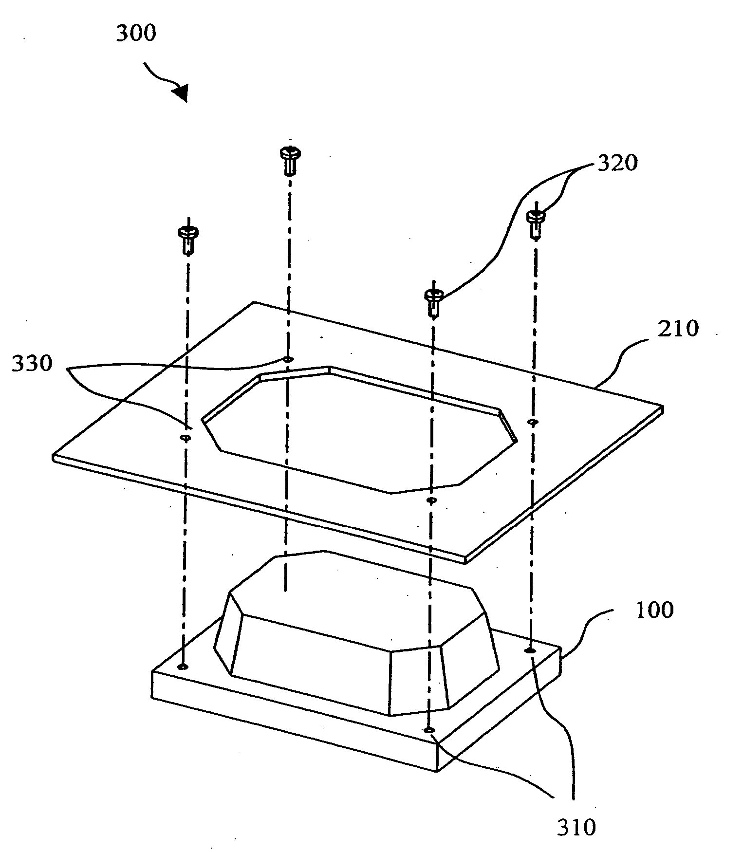
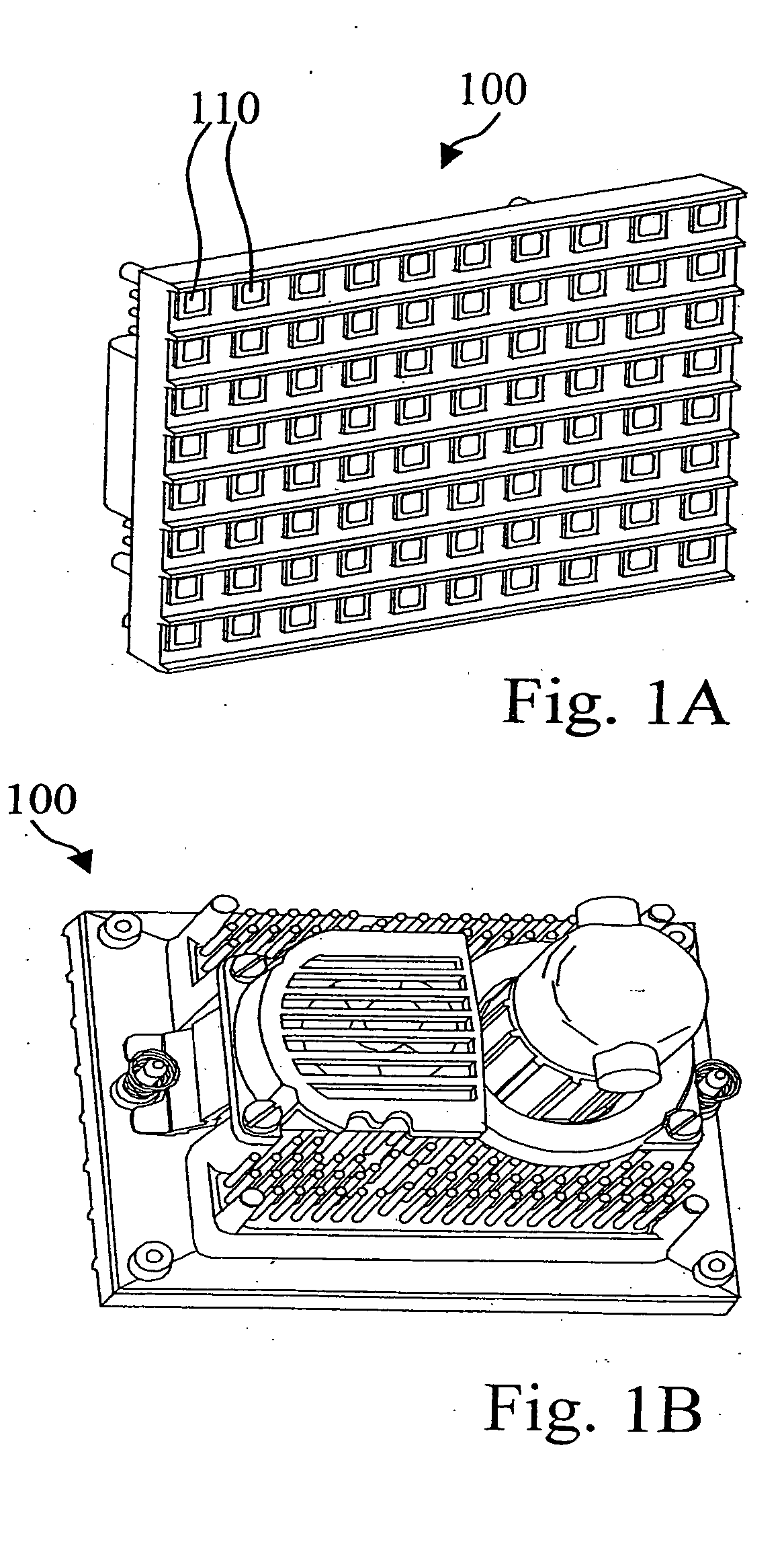
[0031]FIG. 1A illustrates a left perspective view of an exemplary lighting module 100. Lighting module 100 contains a 8×11 array of emissive lighting elements 110; however, is not limited to a 8×11 array; the emissive lighting elements may come in any array size formed of any module size. Lighting module 100 is approximately 84 millimeters (mm) high by 112 mm wide by 50 mm deep; however, it is not limited to these dimensions. Lighting module 100 is designed for large-scale modular displays.

[0032]FIG. 1B illustrates a rear right perspective view of lighting module 100.

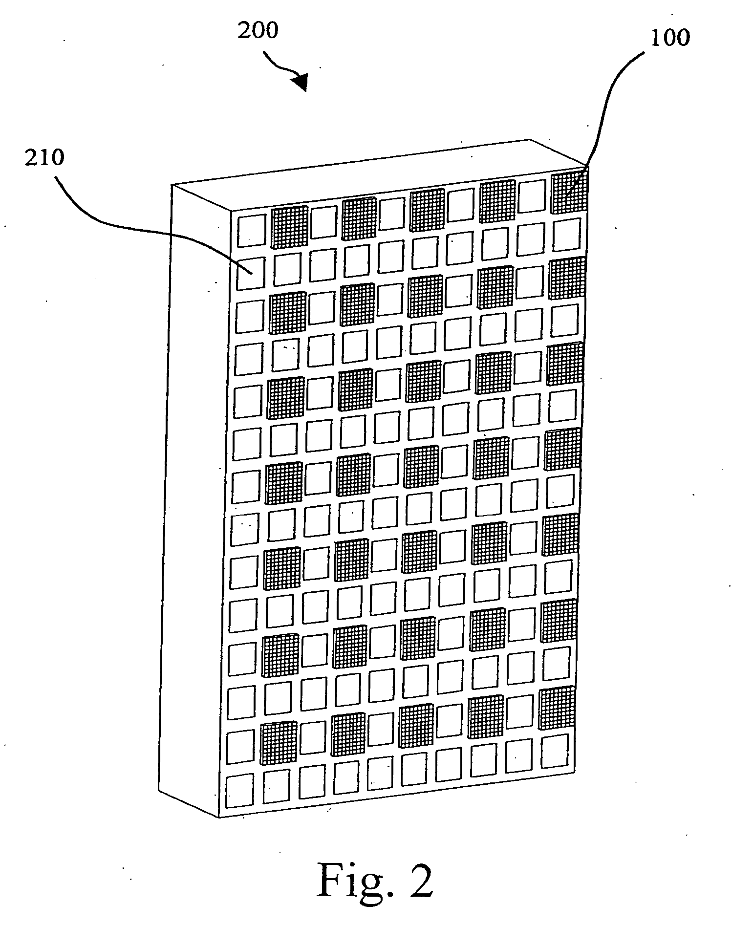
[0033]FIG. 2 illustrates an exemplary display panel system. Display panel system 200 is formed of a 10×15 array of display panel slots 210, but is not limited to the 10×15 array size. Lighting modules 100 are placed in display panel slots 210 as desired.

[0034] Display panel system 200 is designed to be placed adjacent to any number of other display panels 200 in order to create a large-scale display (not shown).

[003...


PUM


Abstract

A display element including a display panel on which one or more lighting modules are fastened, wherein the display element further includes a mechanical mounting interface for fastening said lighting module to the display panel.

Description

BACKGROUND OF THE INVENTION [0001] 1. Field of the Invention [0002] The present invention relates to a mechanical mounting interface for a lighting display module and complimentary mechanical panel or frame for use in large-scale display applications. In particular, the present invention relates to an interchangeable mounting mechanism for quickly installing, maintaining, and disassembling LED, OLED or other emissive modular large-scale display. [0003] 2. Discussion of the Related Art [0004] Conventional incandescent lamps, fluorescent lamps, and neon tubes have long been used to illuminate many large-scale commercial and public signs. However, the market is now demanding cheaper and larger displays that have the flexibility to customize display sizes and colors, that have image and video capability, and that are easy to install, maintain, and disassemble, especially for use in temporary venues; these are market specifications that are not possible with the older technologies. As a ...

Claims


Application Information

Patent Timeline
IPC IPC(8): B60Q1/00F21V7/04H05B44/00
CPCG06F3/14G09F27/008G06F3/1446G09F9/30G09F9/33G09F15/00G09F19/22G09G3/2014G09G3/32G09G3/3611G09G5/003G09G2300/026G09G2360/04G09G2370/04G09G2370/042G09G2370/045H04N5/70H04N9/12H04N9/30H04N13/0404H05B37/02H05B37/0254Y02B20/48G09F9/3026H04N2213/001G06F3/1431H04N13/305H05B47/18H05B47/10Y02B20/40G09F9/335
Inventor THIELEMANS, ROBBIEVAN HILLE, HERBERTMEERSMAN, KARIMDE KEUKELEIRE, STEVEN
Owner BARCO NV
Learn More