Connector supporting tool, wiring tool and wiring harness

a technology of supporting tool and connector, which is applied in the direction of insulated conductors, coupling device connections, cables, etc., can solve the problems of increasing the number of parts, reducing the number of reducing the time required for fixing connectors on wires at predetermined positions. , the rigidity of the connector supporting tool is increased, and the man-hours and production costs are small

Inactive Publication Date: 2013-01-10
AUTONETWORKS TECH LTD +2
View PDF5 Cites 7 Cited by
  • Summary
  • Abstract
  • Description
  • Claims
  • Application Information

AI Technical Summary

Benefits of technology

[0020]The above-described connector supporting tool has a plate with projections, recesses and grooves formed in parts thereof. This member is obtained by applying vacuum forming to a flat resin plate or by injection molding using a simple mold including no sliding mechanism, and man-hours and cost required for production are small.
[0021]The plural connector supports on one wiring tool enables plural connectors to be fixed at one time at specified positions of a supporting body, such as a panel of an automotive vehicle, merely by attaching one wiring tool to the supporting body. Thus, the time required for fixing connectors on wires at predetermined positions can be reduced.
[0022]The respective boundary parts between the sides of the intermediate plate and the parallel recesses preferably are cut inward. Thus the intermediate plate engages the beam in the coupling of the connector in a more stable state and makes the connector less likely to separate from the connector supporting tool.
[0023]The inner recess that connects the pair of grooves preferably is formed in the connector supporting tool because the rigidity of the connector supporting tool that is a plate-like member with projections and recesses is increased.
[0024]Members obtained by applying vacuum forming to a flat plate generally can be produced more easily and at lower cost than members obtained by resin injection molding. Thus, forming the above-described connector supporting tool by applying vacuum forming to a flat plate reduces production man-hours and cost. Note that the base including the rib disclosed in Japanese Unexamined Patent Publication No. 2010-27242 and the connector mounting clamp disclosed in Japanese Unexamined Patent Publication No. H08-195253 cannot be obtained by applying vacuum forming to a flat plate.

Problems solved by technology

H08-195253 has a relatively complicated three-dimensional shape and requires an injection molding process using a slide mold.
H08-195253 has a problem of relatively many man-hours and high cost required for production.
Thus, in the case of fixing plural connectors on plural wires of a wiring harness, the number of parts increases and man-hours for parts management and time required for an operation of individually fixing plural connectors to a supporting body via connector mounting clamps drastically increase.
Such operations are very cumbersome.

Method used


Image

  • Connector supporting tool, wiring tool and wiring harness
  • Connector supporting tool, wiring tool and wiring harness
  • Connector supporting tool, wiring tool and wiring harness

Examples


Embodiment Construction

[0042]A particular embodiment of the invention is described with reference to the accompanying drawings. The following embodiment is a specific example of the invention and does not limit the scope of the invention.

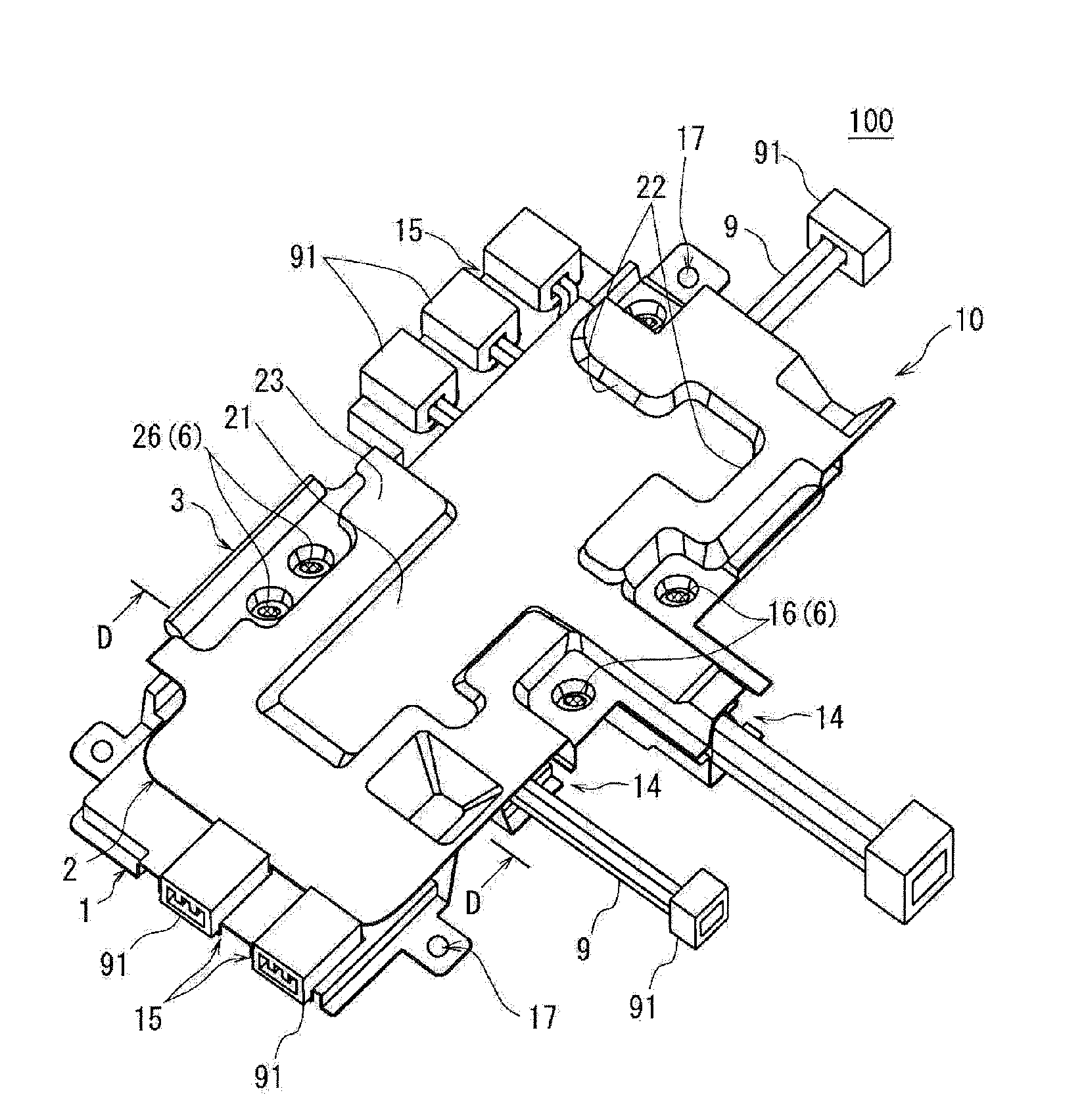
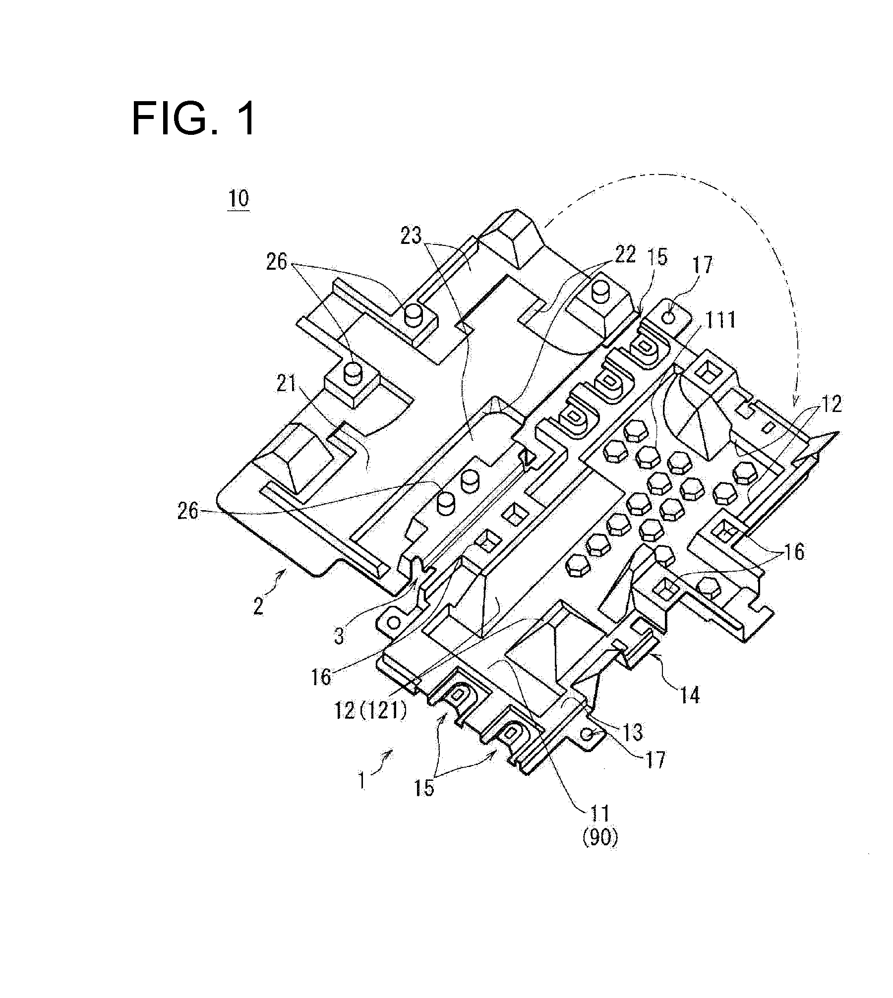
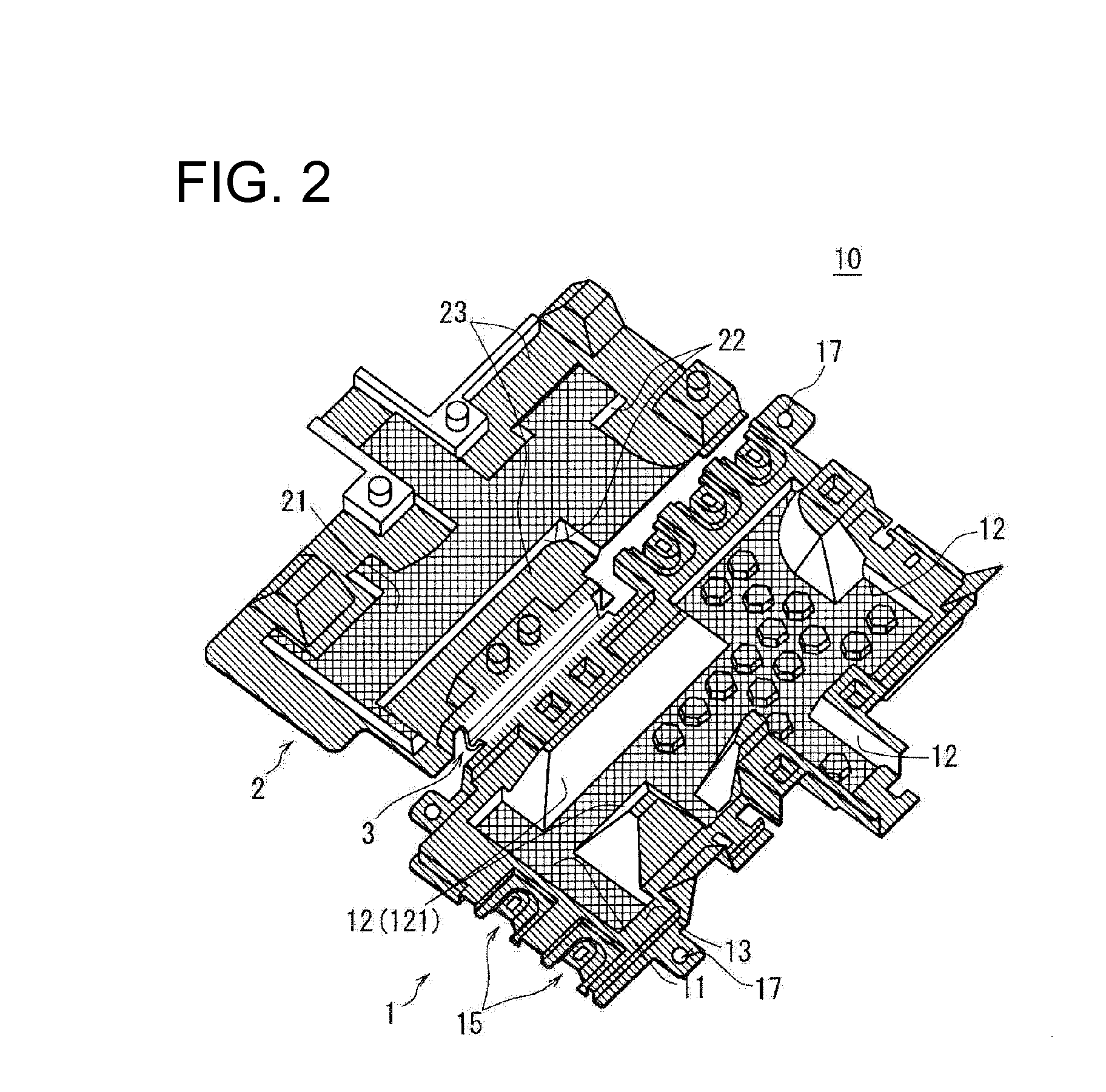
[0043]The invention includes a wiring tool 10 and a wiring harness 100 as shown in FIGS. 1 to 5. The wiring harness 100 includes a wire set comprising plural wires 9 and the wiring tool 10 attached to the wire set. The wiring harness 100 is to be mounted, for example, in a space below a seat, a space under the roof or in the trunk of a vehicle and is connected to other wires and / or wiring devices. The wires 9 of the wiring harness 100 are connector-connected wires composed of insulated wires and a connector 91 mounted on ends of the insulated wires.

[0044]The wires 9 of the wiring harness 100 are united by the wiring tool 10 while being held in specified shapes. Thus, the wiring harness 100 can be mounted easily at a predetermined position using a fixing device, such as a ...


PUM

PropertyMeasurementUnit
shapeaaaaaaaaaa
distanceaaaaaaaaaa
shapesaaaaaaaaaa

Abstract

A wiring tool for holding wires has a plate-like member with connector support (15) that supports a connector (91) by engaging a coupling portion (92) of the connector (91). The connector support (15) has two parallel recesses (151) that form parallel grooves extending straight in from an outer edge of the plate-like member. Two parallel projections (921) of the coupling (92) are fit into the grooves. An intermediate plate (152) of the connector support (15) is between the parallel recesses (151) and is inserted into a clearance between the outer surface of the connector (91) and a beam (922) of the coupling (92). The intermediate plate (152) has a hole (153) that engages a facing projection (923) formed on the beam (922).

Description

BACKGROUND OF THE INVENTION[0001]1. Field of the Invention[0002]The invention relates to a connector supporting tool for supporting a connector, a wiring tool for holding connector connected wires in predetermined shapes and a wiring harness including the same.[0003]2. Description of the Related Art[0004]A wiring harness mounted in a vehicle, such as an automotive vehicle, may include a wiring tool made of resin. The wiring tool is attached to wires and is laid with the wires held along paths predetermined by the wiring tool. For example, wires in a conventional wiring harness may be fixed to a plate-like or bar-like resin member by a binding member, such as an adhesive tape or a belt to hold the wires in predetermined shapes.[0005]Japanese Unexamined Patent Publication No. 2010-27242 discloses a wiring harness with a wiring tool composed of a plate-like resin base and a plate-like resin cover fixed together by heat pressing while sandwiching a wire bundle. A rib stands up from the ...

Claims


Application Information

Patent Timeline
Patent Type & Authority Applications(United States)
IPC IPC(8): H02G3/04H01B7/00
CPCH01R13/6273H02G3/30H01R43/20B60R16/02H01R13/73H02G3/02
Inventor FUJIOKA, RYOSUKEYAMANO, YOSHIAKIKASAMATSU, ATSUSHIYAMASHITA, HIROSHI
Owner AUTONETWORKS TECH LTD
Why Eureka
Try Eureka