Biomass fuel aluminum melting furnace

A biomass fuel, aluminum melting furnace technology, applied in furnaces, crucible furnaces, furnace types, etc., can solve the problems of low heat exchange efficiency between flame and crucible, increase the production cost of molten aluminum, and large temperature fluctuations of the crucible, and achieve stable use. Good performance, saving fuel cost and reducing energy consumption

Inactive Publication Date: 2014-08-20
NINGBO YILONG NEW ENERGY CO LTD
View PDF8 Cites 9 Cited by
  • Summary
  • Abstract
  • Description
  • Claims
  • Application Information

AI Technical Summary

Problems solved by technology

The prior art biomass fuel aluminum melting furnace, for example, the publication number is CN103471389A, and the name is a Chinese patent application for a biomass fuel melting aluminum furnace. The biomass fuel aluminum melting furnace includes a furnace body and a crucible, and the furnace body is provided with a heating The crucible is placed in the heating chamber, and there is a support block for supporting the crucible at the bottom of the heating chamber. The heating chamber and the combustion chamber are connected through the flame inlet; After reaching the crucible, most of the flame rises directly and is discharged from the smoke outlet, which reduces the contact area with the flame when the crucible is heated, making the heating speed of the crucible slower and the heating efficiency lower; at the same time, the flame comes out of the flame inlet directly If it is sprayed on the area of ​​the crucible facing the flame inlet, the temperature in this area will rise faster, and the crucible will be prone to cracking due to uneven heating, resulting in a shorter service life of the crucible; After coming out, it is directly sprayed on the area of ​​the crucible facing the flame passage, while other areas of the crucible have less contact with the flame, which makes the heat exchange efficiency between the flame and the crucible lower, resulting in greater fuel consumption and energy consumption. The temperature of the crucible The fluctuation is also large, the stability is poor, and the production cost of molten aluminum is also increased

Method used


Image

  • Biomass fuel aluminum melting furnace
  • Biomass fuel aluminum melting furnace
  • Biomass fuel aluminum melting furnace

Examples


Embodiment Construction

[0019] The present invention will be further described below in conjunction with the accompanying drawings and specific embodiments.

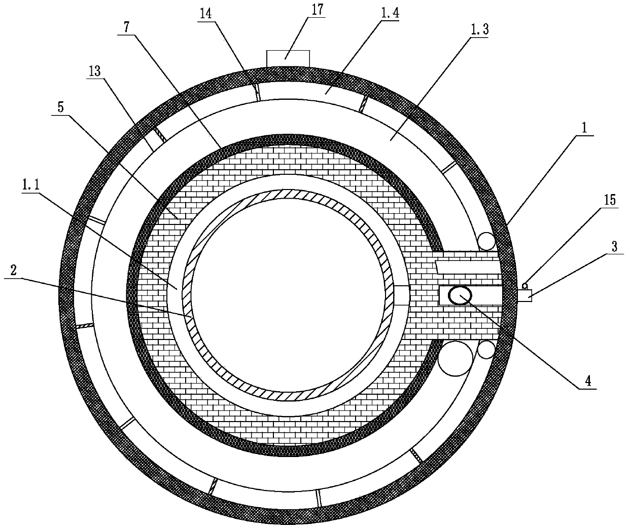
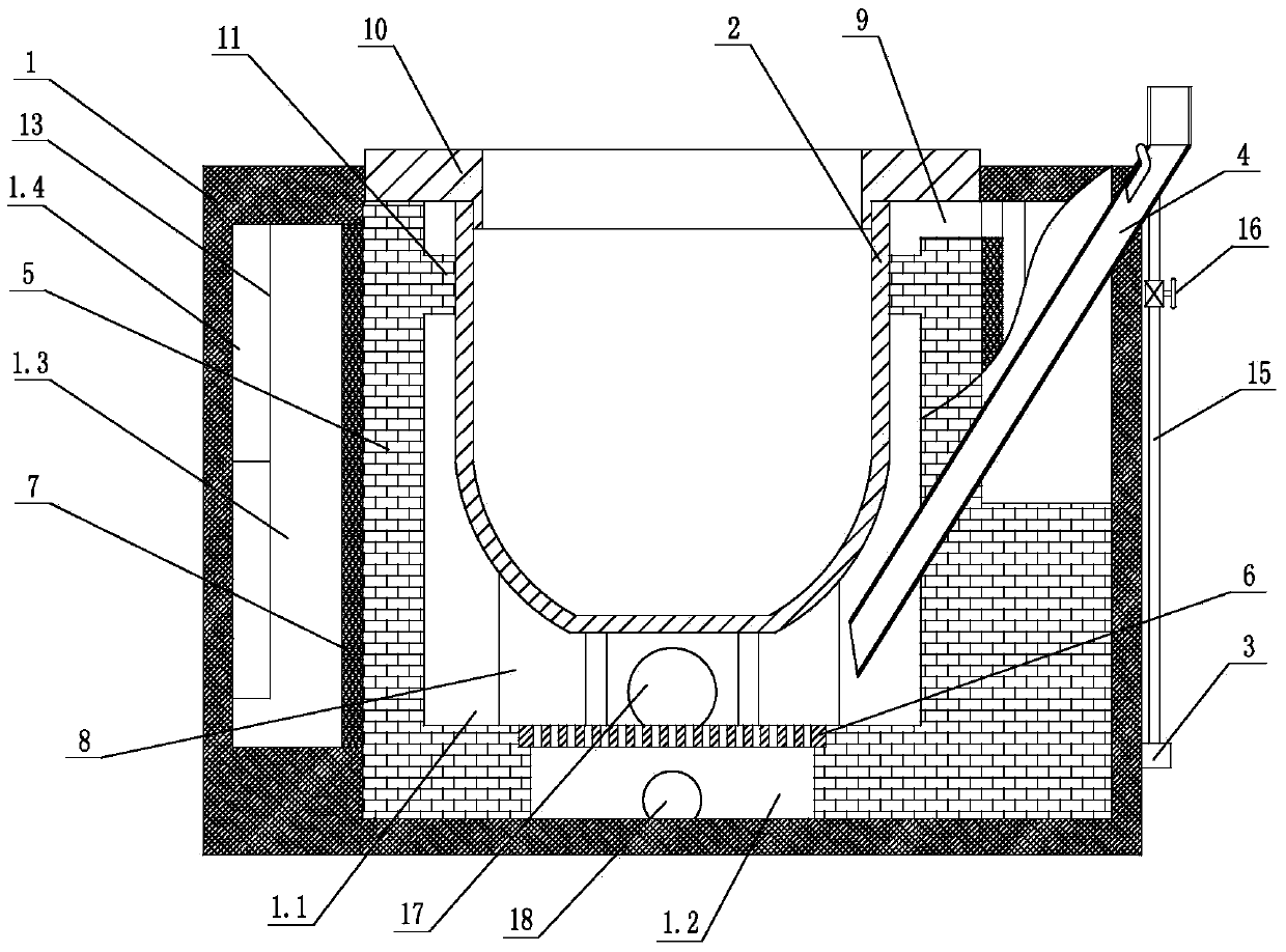
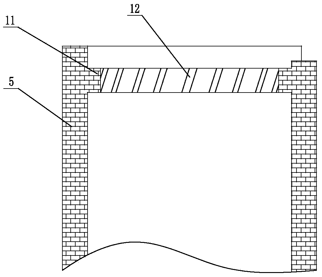
[0020] Such as figure 1 , figure 2 and image 3 Shown, a kind of biomass fuel melting aluminum furnace, it comprises furnace body 1, crucible 2, air inlet 3 and feed pipe 4 (certainly also comprises other parts, but because do not relate to the invention point that the present invention creates, so in This will not be repeated), the furnace body 1 is provided with a cavity separated by the refractory brick layer 5, and the combustion chamber 1.1 and the ash chamber 1.2 are arranged in the cavity, and the combustion chamber 1.1 passes through the grate 6 It communicates with the furnace ash chamber 1.2, the air inlet 3 is located at the lower end of the furnace body 1, the crucible 2 is located in the combustion chamber 1.1, and the outer periphery of the refractory brick layer 5 corresponding to the combustion chamber 1.1 is covered with hea...


PUM


Abstract

A biomass fuel aluminum melting furnace comprises a furnace body (1), a crucible (2), an air inlet (3) and a feeding pipe (4). A cavity is arranged in the furnace body (1) and is formed by separating the furnace body (1) through a refractory brick layer (5). A smoke channel (1.3) and a gas inlet channel (1.4) are arranged in the space between the refractory brick layer (5) and the inner wall of the furnace body (1) and is formed by separating the furnace body (1) through a heat-conducting material layer (13), wherein the inlet and the outlet of the smoke channel (1.3) are located at the two ends of a C-shaped structure respectively, the inlet and the outlet of the gas inlet channel (1.4) are also located at the two ends of the C-shaped structure respectively, the inlet of the gas inlet channel (1.4) is communicated with the air inlet (3), and the outlet of the gas inlet channel (1.4) is communicated with an ash chamber (1.2). One end of the feeding pipe (4) is located in a combustion chamber (1.1), and the other end of the feeding pipe (4) is located outside the furnace body (1). Compared with the prior art, the biomass fuel aluminum melting furnace has the advantage that the crucible is capable of being evenly heated, long in service life, high in heat exchange efficiency, low in energy consumption, good in use stability and low in aluminum melting production cost.

Description

technical field [0001] The invention relates to a biomass fuel aluminum melting furnace. Background technique [0002] Biomass fuel aluminum melting furnace refers to an aluminum melting furnace that is heated by burning solid biomass fuel. The prior art biomass fuel aluminum melting furnace, for example, the publication number is CN103471389A, and the name is a Chinese patent application for a biomass fuel melting aluminum furnace. The biomass fuel aluminum melting furnace includes a furnace body and a crucible, and the furnace body is provided with a heating The crucible is placed in the heating chamber, and there is a support block for supporting the crucible at the bottom of the heating chamber. The heating chamber and the combustion chamber are connected through the flame inlet; After reaching the crucible, most of the flame rises directly and is discharged from the smoke outlet, which reduces the contact area with the flame when the crucible is heated, making the heat...

Claims


Application Information

Patent Timeline
IPC IPC(8): F27B14/08F27B14/14F27B14/16
Inventor 吴伟林吴伟良
Owner NINGBO YILONG NEW ENERGY CO LTD
Why Eureka
Try Eureka