Motion detection apparatus and motion detection method

a technology of motion detection which is applied in the field of motion detection apparatus and motion detection method, can solve the problems of large amount of calculations, increased detection errors, and need for enormous quantities of calculations, and achieve the effect of minimal errors and simple implementation

Inactive Publication Date: 2006-04-13
NISSAN MOTOR CO LTD +1
View PDF8 Cites 27 Cited by
  • Summary
  • Abstract
  • Description
  • Claims
  • Application Information

AI Technical Summary

Benefits of technology

[0014] To addressing the above issues, the present invention has an aim to provide a motion detection apparatus and motion detection method wherein by using a procedure with a less amount of data in a relatively simple implementation, a shift speed, a shift direction, and a position of a moving object can be detected from among motion images at a higher speed with a minimal error.

Problems solved by technology

However, since the former needs a global search that calculates a correlation quantity of the brightness for all blocks of the frame image at time t+1 in terms of a reference block of the frame image at time t, there is a need for enormous quantity of calculations.
In other words, in order to calculate the flow vector, the former needs to interpolate the correlation quantity with a higher order curve in a process of the entire search for calculating a position to give an extreme value of the correlation quantity, resulting in a huge amount of calculations.
Further, since the latter is established under the assumption in which the brightness between the adjacent frame images in time series smoothly varies in time, a detection error increases in the absence of this assumption.
Additionally, the latter has complicated procedures.

Method used


Image

  • Motion detection apparatus and motion detection method
  • Motion detection apparatus and motion detection method
  • Motion detection apparatus and motion detection method

Examples


first embodiment

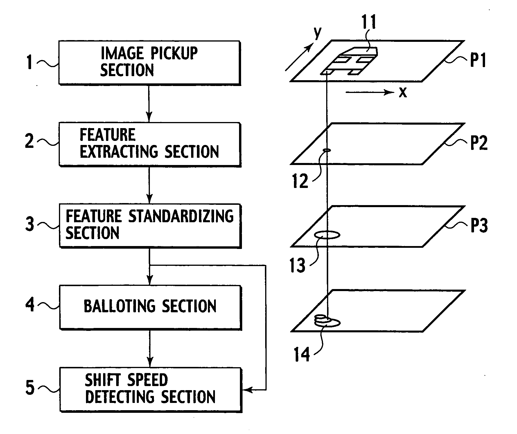
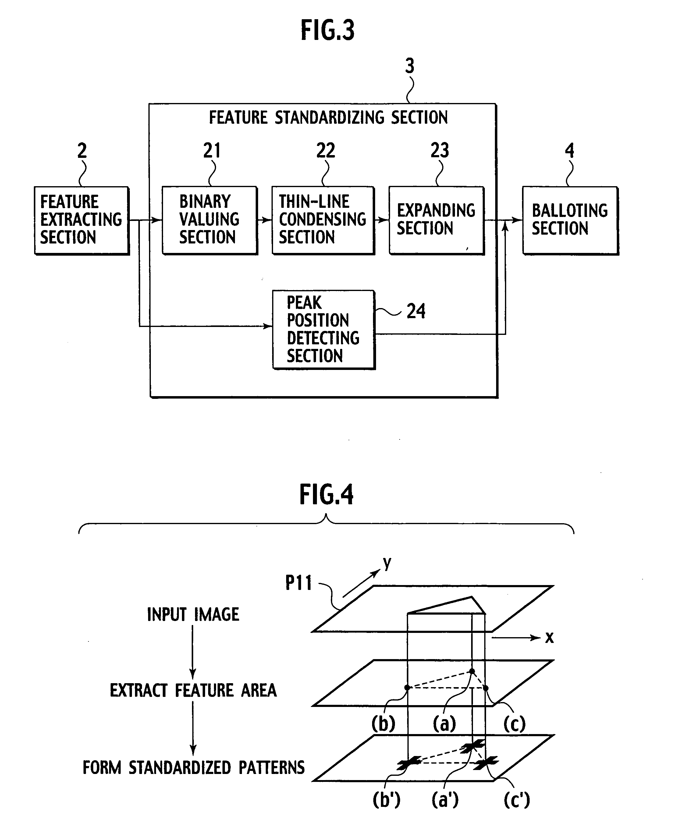
[0045] As shown in FIG. 1, the motion detection apparatus of the presently filed embodiment is comprised of an image pickup section 1, a feature extracting section 2, a feature standardizing section 3, the balloting section 4, and a shift speed detecting section 5.

[0046] The image pickup section 1 is constructed of an image pickup element such as a CMOS (Complementary Metal-Oxide Semiconductor) image sensor and a CCD (Charge Coupled Device) and performs a process for clipping the successively picked-up motion images into frame images each for a fixed interval. In this moment, the frame images are clipped at a frame rate adequately higher than a shift speed of an object to be detected.

[0047] The feature extracting section 2 is inputted with the frame images, including the relevant object, from the image pickup section 1 and performs a given image processing (which will be described below in detail) on the relevant frame images for thereby extracting a feature area representing a fe...

second embodiment

[0095] Now, a motion detection apparatus of a second embodiment is described.

[0096] While with the first embodiment, the standardizing size of the feature areas is set to the given size during the standardizing operation of the feature standardizing section 3, the presently filed embodiment features that in the motion detection apparatus of the first embodiment, further, the standardizing size is altered depending on the shift speed of the object. Other structures are similar to those of the first embodiment and description is suitably omitted. Also, with the presently filed embodiment, an edge is adopted as a feature of an object.

[0097] As shown in FIG. 8, the motion detection apparatus of the presently filed embodiment is comprised of an image pickup section 101, an edge extracting section 102, an edge-width standardizing section 103, a balloting section 104 and a shift speed detecting section 105.

[0098] The image pickup section 101 is constructed of an image pickup element suc...

third embodiment

[0137] Next, a motion detection apparatus of a third embodiment is described below.

[0138] Although in the first embodiment, no particular mention is made to a timing at which a ballot value is reset in balloting operation, the presently filed embodiment features that the motion detection apparatus of the first embodiment is further configured to control the timing at which the ballot value is reset depending on shift speed of an object.

[0139] Other structures are the same as the first embodiment and description is suitably omitted. Also, with the presently filed embodiment, an edge is adopted as a feature of the object.

[0140] As shown in FIG. 13, the motion detection apparatus of the presently filed embodiment is comprised of an image pickup section 211, an edge extracting section 212, an edge-width standardizing section 213, a mask generating section 214, a reset timing generating section 215, a balloting section 216 and a shift speed detecting section 217.

[0141] The image pick...


PUM


Abstract

A motion detection device includes a feature extracting section 2 extracting a feature area of an object from among frame images clipped by an image pickup section 1, a feature standardizing section 3 standardizing a size of a feature area extracted by the feature extracting section 2, a balloting section 4 counting up a ballot value of an image area on a frame image located in a standardized pattern that is standardized by the feature standardizing section 3, and a shift speed detecting section 5 calculating a gradient of a counted-up ballot value and calculating a shift direction, a shift speed and position of a feature area based on the gradient.

Description

BACKGROUND OF THE INVENTION [0001] The present invention relates to a motion detection apparatus and motion detection method in which a moving object is detected from among motion images successively picked up for thereby detecting a shift speed, a shift direction and a position of the moving object. [0002] Proposals have recently been made to develop a variety of vehicle vicinity monitoring systems into practical use for recognizing an area surrounding a motor vehicle, such as circumstances of a leading vehicle and a road conditions in front of the own vehicle during running of the vehicle. [0003] Japanese Patent Application Laid-open No. 2003-67752 discloses a vehicle vicinity monitoring apparatus wherein a given image processing is carried on motion images (motion images in time series), successively picked by a camera, to recognize an area surrounding a motor vehicle. One of such image processing methods has heretofore been known as an analyzing technique utilizing an optical fl...

Claims


Application Information

Patent Timeline
Patent Type & Authority Applications(United States)
IPC IPC(8): G06K9/00
CPCG06T7/0042G06T7/204G06T2207/10016G06T2207/30241G06T2207/30248G06T7/73G06T7/248
Inventor WATANABE, SEIGO
Owner NISSAN MOTOR CO LTD
Why Eureka
Try Eureka