
Transition adaptor and component modules for hydronic heating

a technology of transition adaptor and component module, which is applied in the direction of multi-way valve, water/sewage treatment by substance addition, pipe protection against corrosion/incrustation, etc., can solve the problems of many errors, poor practice, and no modular components for connecting, so as to reduce labor and reduce the number of possible errors , the effect of simple and inexpensiv

Inactive Publication Date: 2007-03-20
INVENTIVE DEV
View PDF9 Cites 15 Cited by
  • Summary
  • Abstract
  • Description
  • Claims
  • Application Information

AI Technical Summary

Benefits of technology

"The invention is a system for making hydronic heating systems more modular and easy to assemble with minimal error and labor. It includes a preassembled section of pipe with necessary bends and branch outlets, a main inlet, a branch outlet, a branch inlet, and a main outlet all in fixed relation to each other at a standard distance between them. The main inlet and main outlet are also side-by-side in fixed relation to each other at a set distance from each other. The system also includes a modular supply-return connector that can be easily connected to other modular hydronic heating components. The supply-return connector has appropriate spacing for connecting secondary components such as pumps and valves. The invention simplifies the installation process and reduces labor required and errors."

Problems solved by technology

Although it is known to combine many components that are used between a boiler and the secondary loops into a mechanical module, there are no modular components for making the connections between the boiler and such a mechanical module or between the mechanical module and the secondary loops that make a complete and flexible system.
Preassembling hydronic mechanical modules with many of the normally utilized mechanical parts (for example, but not limited to, pumps, valves, expansion tanks, check valves, etc.) has been attempted in the past, but has been unsatisfactory, since many of the required additional primary, intermediate and secondary components have been required to be field installed, often sweated in place or field fabricated resulting in many errors, poor practice, poor hydronic design, and has been very labor intensive.

Method used


Image

  • Transition adaptor and component modules for hydronic heating
  • Transition adaptor and component modules for hydronic heating
  • Transition adaptor and component modules for hydronic heating

Examples


Embodiment Construction

[0030]In the following detailed description of exemplary embodiments of the invention, reference is made to the accompanying drawings. The detailed description and the drawings illustrate specific exemplary embodiments by which the invention may be practiced. Other embodiments may be utilized, and other changes may be made, without departing from the spirit or scope of the present invention. The following detailed description is therefore not to be taken in a limiting sense, and the scope of the present invention is defined by the stated claims.

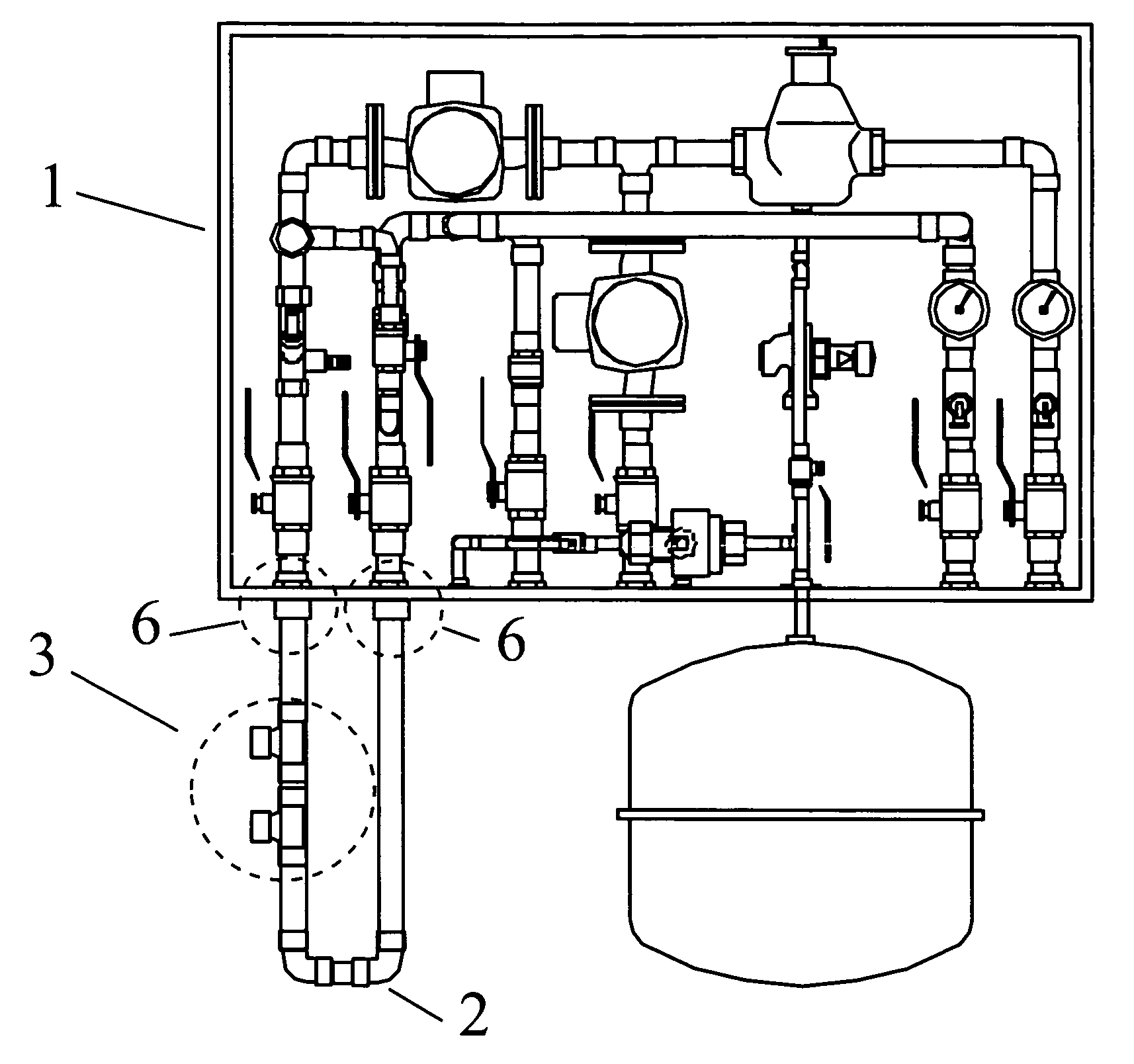
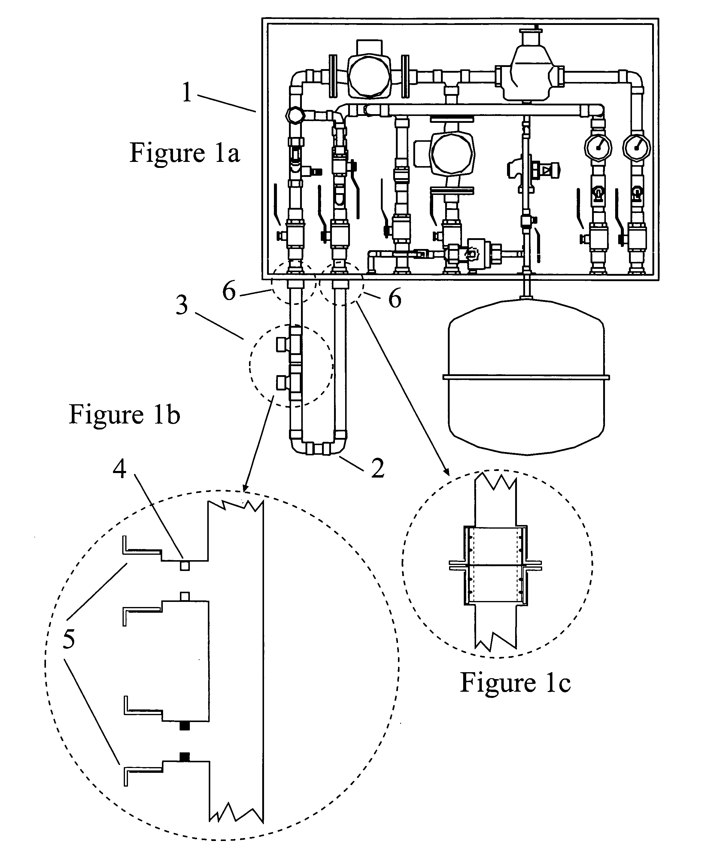
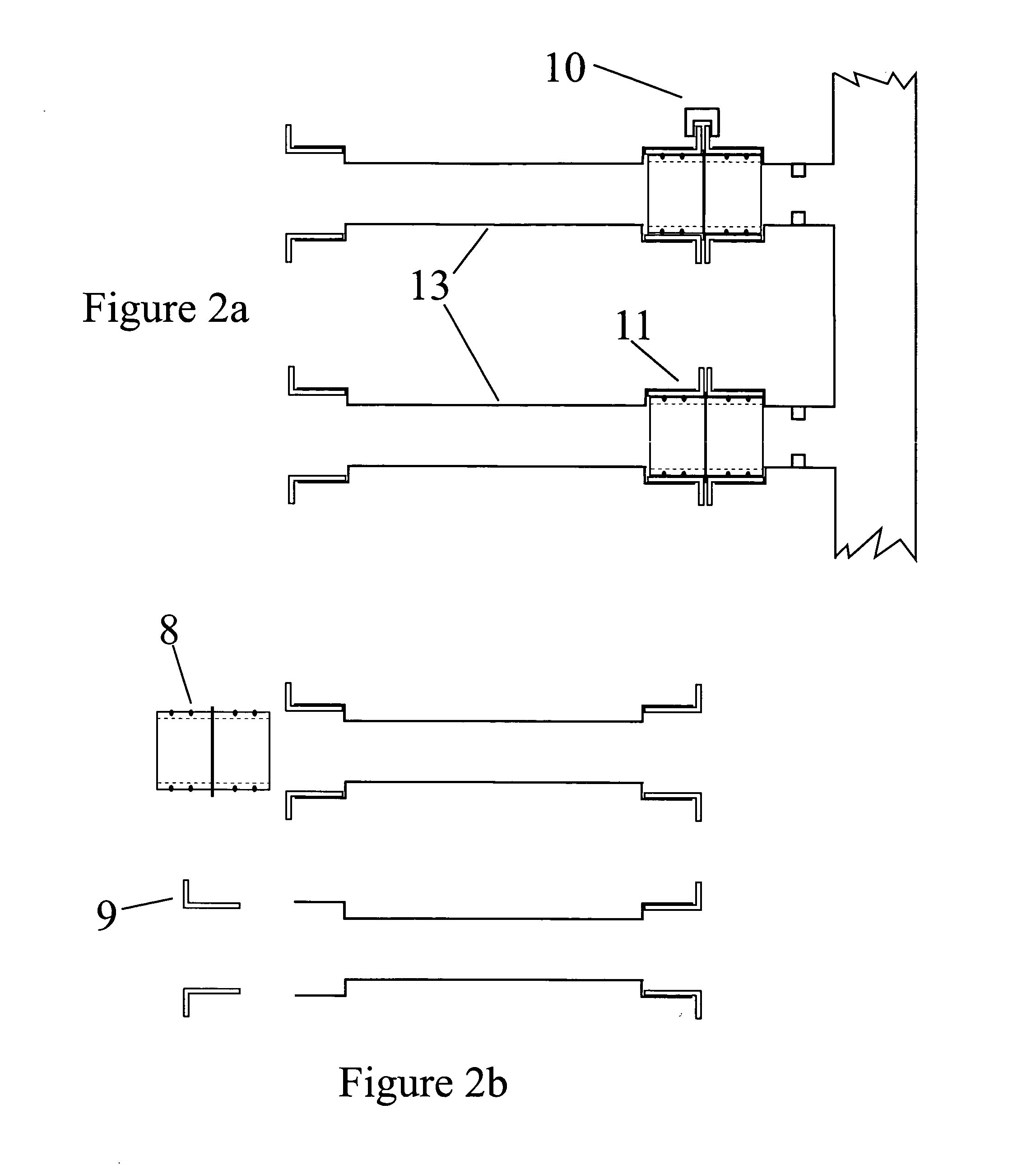
[0031]A transition adaptor 2 is shown in FIG. 1a, designed to facilitate connecting secondary component modules such as Pumping Component Modules, 3-Way Pumping Component Modules, Zone Control Component Modules, and Variable Speed Pumping Component Modules to preassembled intermediate component modules or primary loop component modules and or primary or secondary piping for hydronic heating systems.

[0032]FIG. 1a shows a typical preassembled m...


PUM


Abstract

A system for making modular all of the components of hydronic heating systems so that they can be assembled in various configurations with a minimum of error and labor. The system includes a modular transition adaptor that completes a first hydronic loop and provides a supply outlet and return inlet for servicing a second hydronic loop which is dependent from the first. The transition adaptor has standard spacing and fittings for simple and error free connection to other components such as boilers and mechanical modules. The system also includes a modular supply-return connector that can be connected to the branch outlet and branch inlet of the transition adaptor and to other supply-return connectors. Each supply-return connector includes further branches to provide heated liquid to hydronic radiator loops. The supply-return connectors may include pumps or valves.

Description

[0001]This application claims priority from provisional patent application No. 60 / 467,433, filed May 2, 2003, which is incorporated herein by reference.BACKGROUND[0002]Hydronic heating systems typically include many final heating loops, each of which is adjustable for rate of flow to increase or decrease heat delivered. For optimal performance of pumps and the motors that drive them, it is preferred that each hydronic loop, whether coming directly from the boiler or a sub-loop, not be subjected to a widely varying range of resistance. Consequently, it is common practice to start with a primary loop from the boiler which is driven by a pump, or sometimes convection. The primary loop has low enough resistance to maintain good flow. Tapping off of the primary loop are several secondary loops, each with its own pump that may be turned on and off or varied in speed. Each secondary loop draws hot liquid from a secondary outlet off the primary loop and injects return liquid through a secon...

Claims


Application Information

Patent Timeline
Patent Type & Authority Patents(United States)
IPC IPC(8): F24D3/10F24D3/08
CPCF24D3/1058F24D3/08Y10T137/87338Y10T137/0402Y10T137/87362
Inventor CORBETT, JR., A. HOYT
Owner INVENTIVE DEV
Learn More