Ultrasonic cavitating apparatus and ultrasonic doppler flow measurement system

Inactive Publication Date: 2006-04-13
KK TOSHIBA +1
View PDF5 Cites 22 Cited by
  • Summary
  • Abstract
  • Description
  • Claims
  • Application Information

AI Technical Summary

Benefits of technology

[0015] The ultrasonic Doppler flow measurement system is capable of surely achieving Doppler flow measurement by generating bu

Problems solved by technology

However, when the inner surface of the pipe has a high surface roughness or when the inner surface of the pipe is covered with a cladding of, for example, rust, the accuracy of measurement by the above method lowers depending

Method used


Image

  • Ultrasonic cavitating apparatus and ultrasonic doppler flow measurement system
  • Ultrasonic cavitating apparatus and ultrasonic doppler flow measurement system
  • Ultrasonic cavitating apparatus and ultrasonic doppler flow measurement system

Examples


first embodiment

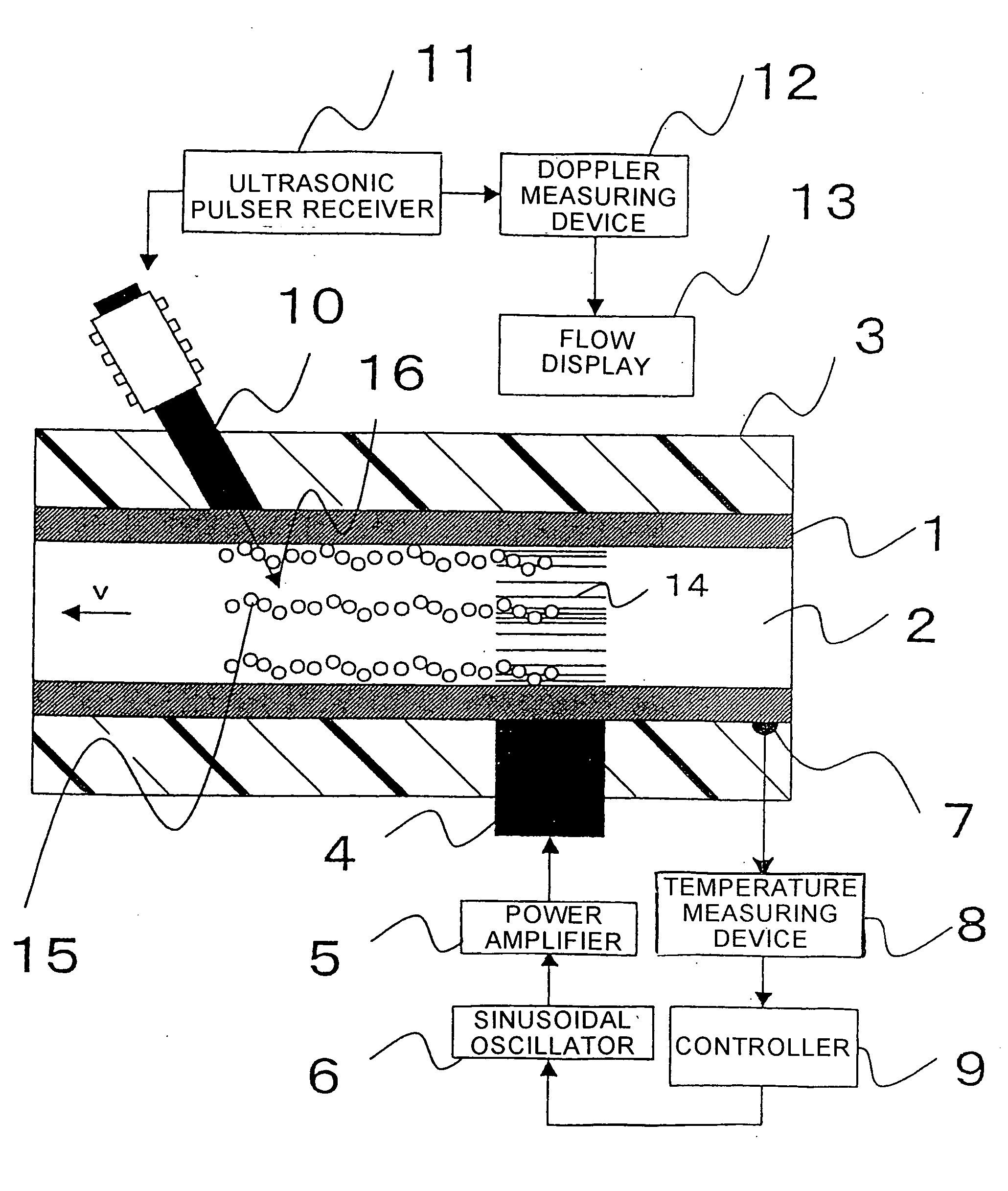
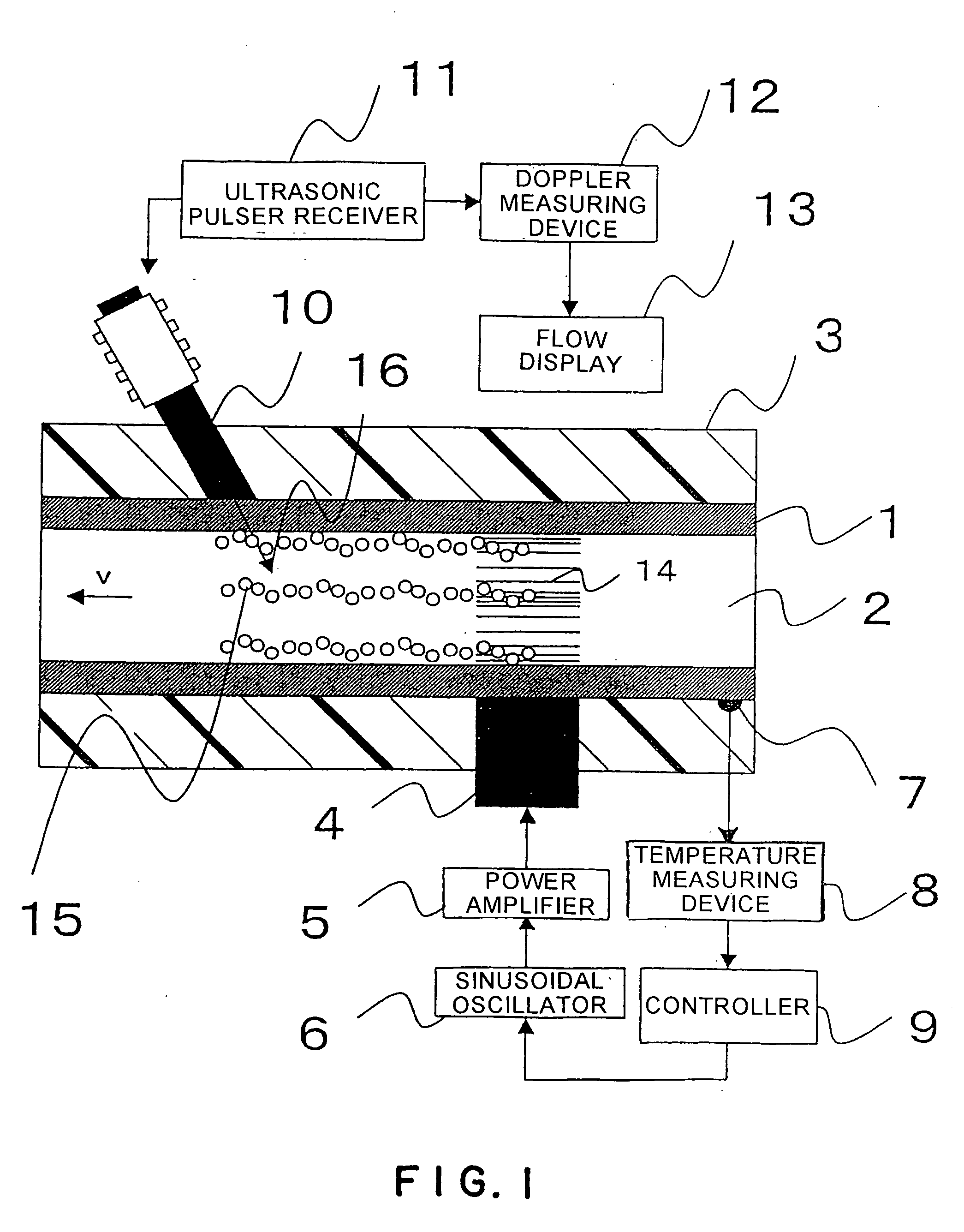
[0026]FIG. 1 is a schematic cross-sectional view of an ultrasonic flow measurement system in a first embodiment according to the present invention. A high-temperature fluid 2 flows through a pipe 1. The pipe 1 is wrapped in a heat insulator 3. An ultrasonic transducer 4 for causing cavitation is mounted to the pipe 1. The ultrasonic transducer 4 is connected to a power amplifier 5. The power amplifier 5 is connected to a variable-frequency, sinusoidal wave oscillator 6. A temperature sensor 7 is attached to the pipe 1 to measure the temperature of the high-temperature fluid 2. The temperature sensor 7 is connected to a temperature measuring device 8, which is connected to a controller 9. The controller 9 is connected to the sinusoidal wave oscillator 6. The devices 4, 5, 6, 7, 8 and 9 constitute a cavitating section of the system.

[0027] An ultrasonic sensor 10 for flow measurement, or a measuring ultrasonic transducer, is attached to the pipe 1. Usually, the ultrasonic sensor 10 is...

second embodiment

[0043]FIG. 5 is a view of a second embodiment according to the present invention. The embodiment shown in FIG. 5 differs from the embodiment shown in FIG. 1 in the increased number of ultrasonic transducers for causing cavitation.

[0044] As shown in FIG. 5, an additional ultrasonic transducer 4′ is arranged such that the ultrasonic transducers 4 and 4′ are disposed diametrically opposite to each other on a pipe 1. The ultrasonic transducer 4′ is connected to a power amplifier 5′. The power amplifier 5′ is connected to a sinusoidal oscillator 6′. The sinusoidal oscillator 6′ is also connected to the controller 9. In this embodiment, the controller 9 controls the sinusoidal oscillators 6 and 6′ on the basis of measured data provided by a temperature sensor 7 and a temperature measuring device 8 so that the ultrasonic oscillators 6 and 6′ generate signals of different frequencies, respectively, to generate a standing wave in a fluid 2 in the pipe 1.

[0045] When a frequency as high as a...

third embodiment

[0047]FIG. 7 shows a third embodiment according to the present invention. The embodiment shown in FIG. 7 differs from the embodiment shown in FIG. 1 only in that an ultrasonic delaying material 20, which is made of a material identical to that of the pipe 1, is interposed between an ultrasonic transducer 4 for causing cavitation and the outer surface of the pipe 1. Thus, the energy of an ultrasonic wave can be efficiently transmitted to a fluid through a complex resonance generated between the delaying member 20 and the wall of the pipe 1. According to “Cho-Ompa Gijutu Binran”, Saneyoshi et al., The Nikkan Kogyo Shimbun Ltd., transmittance is improved when the thickness of the delaying material 20 is equal to an odd number times the half wavelength of the ultrasonic wave. In the second embodiment shown in FIG. 5, ultrasonic delaying material 20 may be combined with the two ultrasonic transducers 4 and 4′, respectively, to enhance the sound pressure of the ultrasonic wave in the flui...


PUM


Abstract

Disclosed is an ultrasonic Doppler flow measurment system that achieves flow measurement regardless of the temperature of a fluid. A temperature sensor 7 is combined with a pipe 1 to measure the temperature of a fluid 2. A controller 9 calculates a frequency that will cause cavitation when an ultrasonic transducer 4 exerts an ultrasonic vibration on the fluid 2 on the basis of a temperature measured by the temperature sensor 7 and controls a sinusoidal oscillator 6.

Description

BACKGROUND OF THE INVENTION [0001] 1. Field of the Invention [0002] The present invention relates to an ultrasonic cavitating apparatus for causing cavitation in a fluid flowing through a pipe, and an ultrasonic Doppler flow measurement system employing the ultrasonic cavitating apparatus. [0003] 2. Description of the Related Art [0004] A generally used ultrasonic flow measuring method of measuring the flow rate of a fluid flowing through a pipe uses, for example, propagation time difference method as mentioned in “Cho-Ompa Gijutu Binran (p.746)”, Saneyoshi et al., The Nikkan Kogyo Shimbun Ltd. However, when the inner surface of the pipe has a high surface roughness or when the inner surface of the pipe is covered with a cladding of, for example, rust, the accuracy of measurement by the above method lowers depending on the sectional area of a part having a high surface roughness or the cladding. [0005] A measurement system developed to solve such a problem and applied to practical u...

Claims


Application Information

Patent Timeline
IPC IPC(8): A61H1/00H04R1/32G01F1/66
CPCG01F1/663
Inventor SATO, MICHIONARABAYASHI, TADASHIMORI, MICHITSUGUTEZUKA, KENICHITEZUKA, HIDEAKI
Owner KK TOSHIBA
Why Eureka
Try Eureka