

Bifurcation stent with crushable end and method for delivery of a stent to a bifurcation
a stent and stent technology, applied in the field of stents with crushable ends and methods for delivering stents to bifurcations, can solve the problems of inherently random techniques, affecting blood flow, and preventing further angioplasty procedures from reaching the branch vessel
- Summary
- Abstract
- Description
- Claims
- Application Information
AI Technical Summary
Problems solved by technology
Method used
Image

Examples
Embodiment Construction
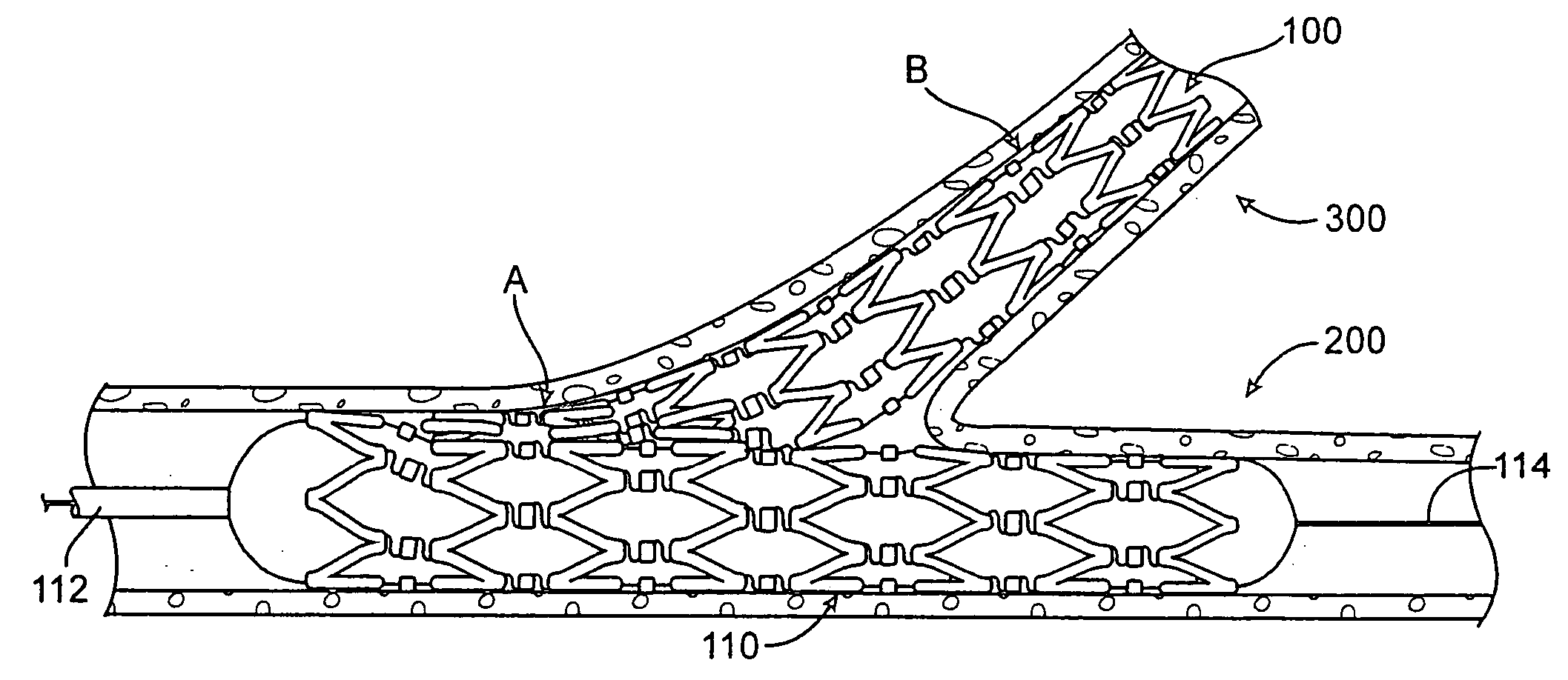
[0025] The term “crush” or “crushed” as used herein refers to the collapsing of one or both opposite sides of a tubular member so that the opposite sides contact or nearly contact one another.
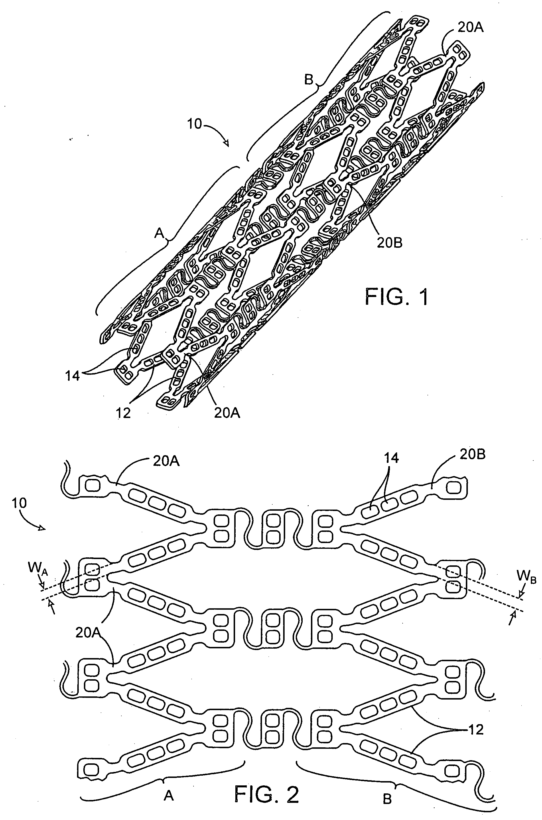
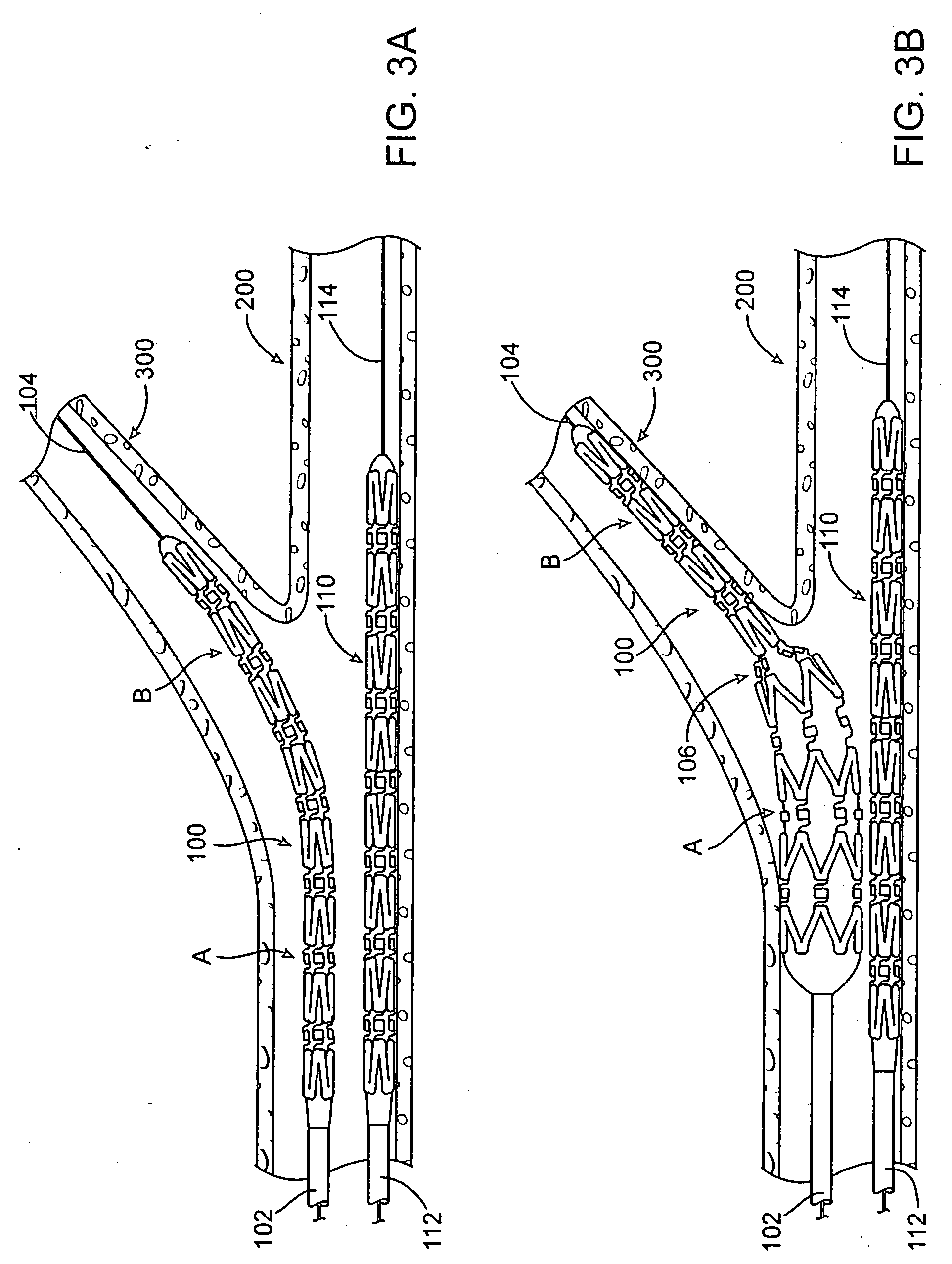
[0026]FIGS. 1 and 2 illustrate one example of a bifurcation stent 10 having a first end A which is deformable or crushable at a lower force than a second end B. The crushable first end A and more rigid second end B of the bifurcation stent allow one end of the stent to remain expanded in tissue supporting configuration in a side branch of a vessel bifurcation while the other end is easily crushed against the side wall of the main vessel into which it extends.
[0027] The stent 10 in the example of FIGS. 1 and 2 has a plurality of struts 12 interconnected by a plurality of ductile hinges 20A and 20B. Upon expansion or compression of the stent, the ductile hinges 20A and 20B plastically deform while the struts are not plastically deformed. The ductile hinges 20A in the crushable end A of the sten...
PUM
 Abstract
Description
Claims
Application Information