Signal end-pointing method and system

Inactive Publication Date: 2006-04-13
FLUENCY VOICE TECHNOLOGY
View PDF6 Cites 22 Cited by
  • Summary
  • Abstract
  • Description
  • Claims
  • Application Information

AI Technical Summary

Benefits of technology

[0019] Moreover, from a yet further aspect the invention also provides a segmentation method and system which uses information from earlier segmentation processes on earlier utterances in the same session to initialise segmentation variables for use in a present segmentation process. This enables much quicker initialisation and hence operation than would otherwise be the case. In view of this, from a fifth aspect there is provided a method of detecting portions of an input signal containing patterns, for subsequent recognition in a pattern rec

Problems solved by technology

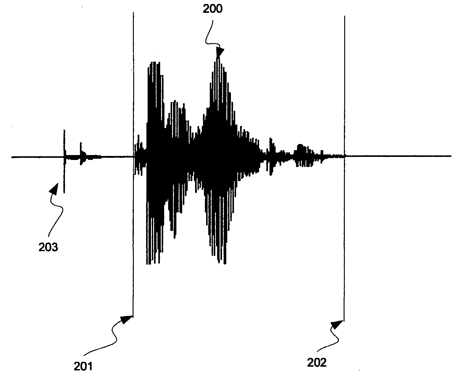
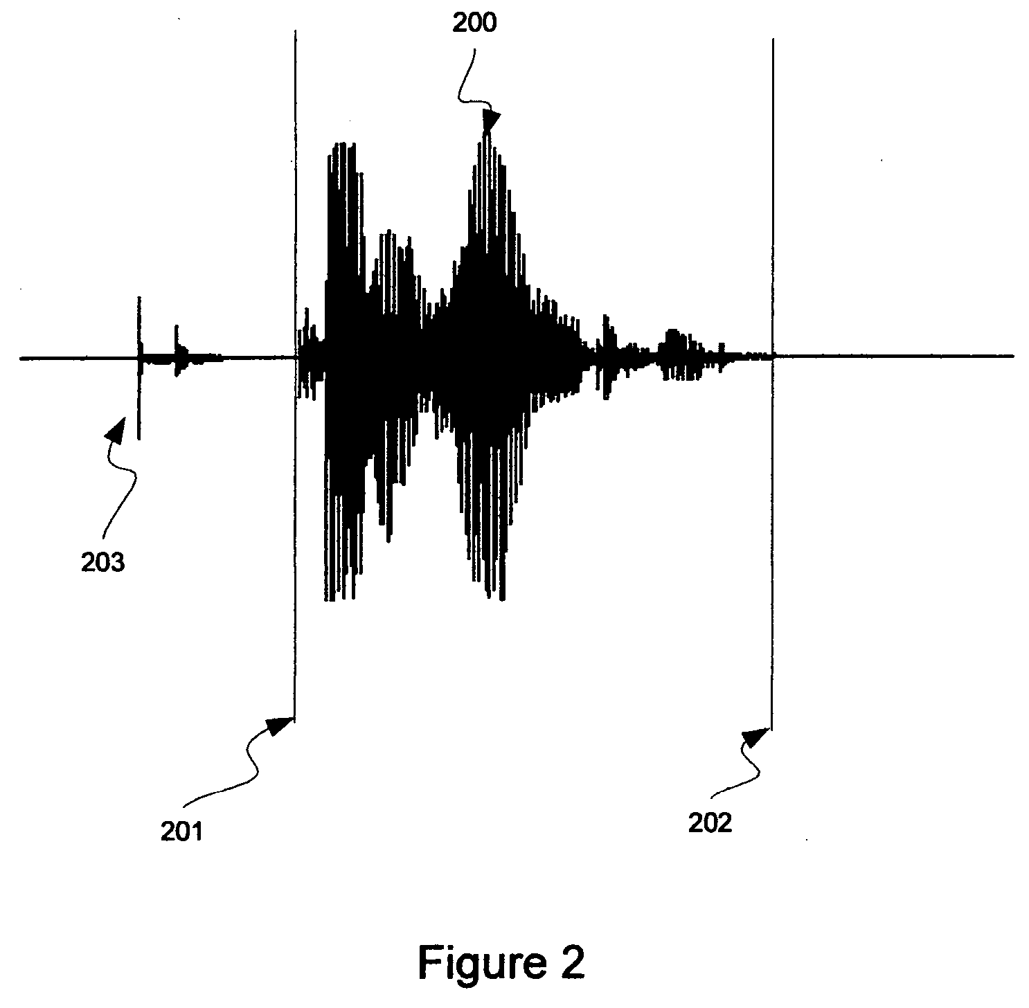
This is challenging because frequently the talker will be talking in a noisy environment, or the talker will be talking in bursts of speech with short pauses between each burst.
If it is slow to identify the end of the speech, the talker may consider that there is a problem with the system, as it will appear to not have heard the caller.
If the end pointer fails to locate the correct portion of the signal, then a recognition error is certain to occur.
Equally, if the end pointer decides too quickly that the

Method used


Image

  • Signal end-pointing method and system
  • Signal end-pointing method and system
  • Signal end-pointing method and system

Examples


Embodiment Construction

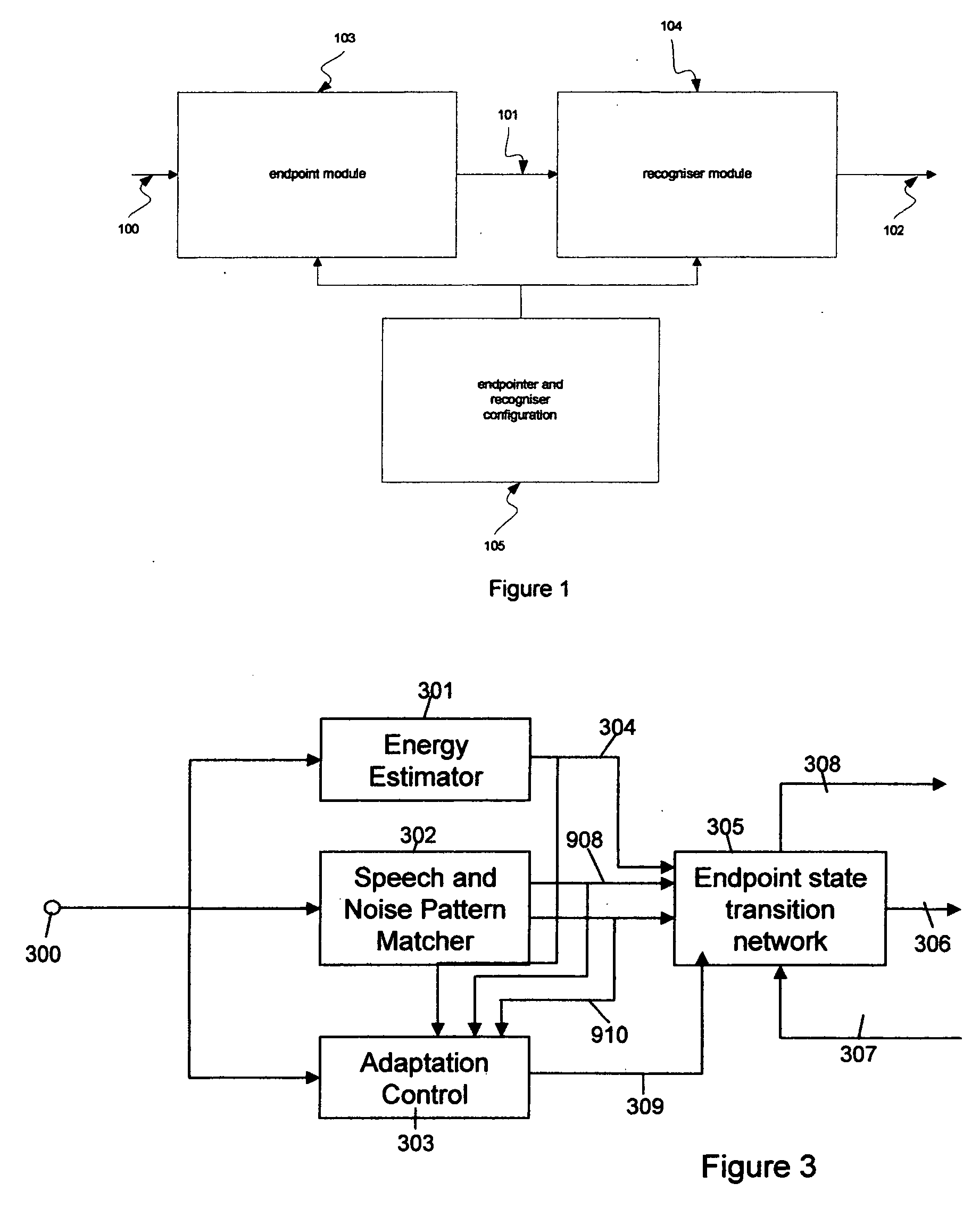
[0036] An embodiment of the present invention will now be described with respect to FIGS. 3 to 13.

[0037]FIG. 13 is a block diagram illustrating a computer system which may embody the present invention, and the context in which the computer system may be operated. More particularly, a computer system 1300 which may be conventional in its construction in that it is provided with a central processing unit, memory, long term storage devices such as hard disk drives, CD ROMs, CD-R, CD-RW, DVD ROMs or DVD RAMs, or the like, as well as input and output devices such as keyboards, screens, or other pointing devices, is provided. The computer system 1300 is, as mentioned, provided with a data storage medium 1302, such as a hard disk drive, floppy disk drive, CD ROM, CD-R, CD-RW, DVD ROM or RAM, or the like upon which is stored computer programs arranged to control the operation of the computer system 1300 when executed, as well as other working data. In particular, operating system program 1...


PUM


Abstract

A method of improving pattern recognition accuracy is provided that uses a mechanism for locating a pattern within an input signal, such as provided by a telephone network. This operation is hard because of the variability of the signal that is likely to be received by the pattern recogniser. It will receive a large range of signal amplitudes, possibly embedded in a variety of background noises, and is required to produce its best hypothesis of the patterns in this signal. This invention concerns the identification of the location of the patterns within the input signal, which in some aspects uses feedback from the following pattern matcher, and in other aspects uses a pattern distance to noise distance ratio to determine the pattern identification. Other aspects are also described. It is important to accurately locate the pattern to be recognised as errors in the location of the pattern will result in errors in the recognition of the pattern. The patterns to be recognised are preferably human utterances.

Description

CROSS-REFERENCE TO RELATED APPLICATION [0001] This application is related to, and claims a benefit of priority under one or more of 35 U.S.C. 119(a)-119(d) from copending foreign patent application GB0421642.0, filed in the United Kingdom on Sep. 29, 2004 under the Paris Convention, the entire contents of which are hereby expressly incorporated herein by reference for all purposes. BACKGROUND INFORMATION [0002] 1. Field of the Invention [0003] The present invention relates to a method and system for identifying the end-point of a wanted signal for use with a pattern recognition process, such as, for example, identifying a spoken utterance within an audio signal for use with a speech recogniser. [0004] 2. Discussion of the Related Art [0005] Computer-based speech recognisers are known in the art, and in particular for use within call-centre applications, wherein speech to be recognised is received over a voice (typically a POTS) channel. In such applications, the caller maintains a d...

Claims


Application Information

Patent Timeline
IPC IPC(8): G10L19/14G10L15/10G10L25/87
CPCG10L15/10G10L25/87G10L15/08
Inventor THOMAS, TREVORTAN, BENG TIONG
Owner FLUENCY VOICE TECHNOLOGY
Why Eureka
Try Eureka