
Water intrusion prevention method and apparatus

a technology of water intrusion prevention and water pipe, which is applied in the direction of snow traps, frame fastenings, doors/windows, etc., can solve the problems of rotting inside the framing, and achieve the effects of reducing the space, and reducing the risk of water intrusion

Inactive Publication Date: 2006-04-20
T STOP PROD LLC
View PDF11 Cites 20 Cited by
  • Summary
  • Abstract
  • Description
  • Claims
  • Application Information

AI Technical Summary

Benefits of technology

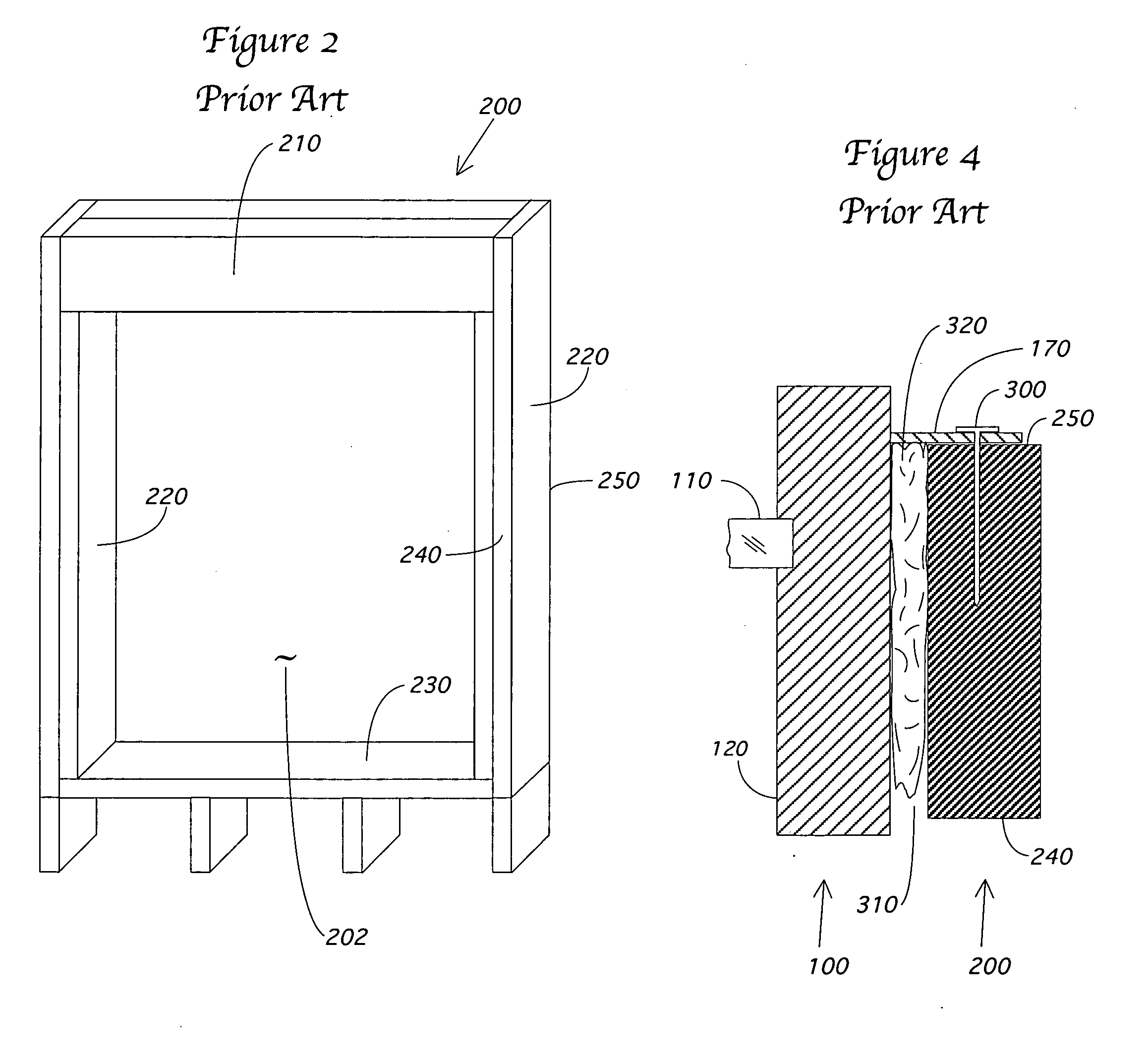
[0009] The present invention prevents moisture that enters the window opening from entering the interior of the building by creating a channel behind the nailing flange of the window. Prior art windows and techniques encouraged foam insulation to be inserted between the window and the rough opening all the way to the nailing flange that is used to secure the window. This insulation prevented moisture from reaching the sill, from which it could drain or evaporate. Instead, the foam directed the water into the interior of the building. Alternatively, water that did reach the sill could become trapped behind the insulation and be prevented from draining or evaporating. In this case, the water may cause rotting inside the framing.
[0010] The present invention creates a barrier in the space between the window and the rough opening that prevents the foam from reaching the nailing flange. On the interior side of this barrier, the foam is installed normally. On the exterior side of this barrier a channel is created. This channel preferably runs around the circumference of the window. The channel allows water that enters behind the nailing flange the ability to drain down to the window sill where it can drain or evaporate.
[0012] The gasket can be attached to the window during window manufacture. Alternatively, the gasket can be sold separately and attached to the window at the installation site. The gasket may also be directly attached to the rough opening itself, where it will then engage the window frame when the window is installed. The gasket can be relatively straight, extending perpendicularly from the window or rough opening and then bending during window installation. Alternatively, the gasket can be curved. The curved gasket can be sized large enough to span a large space between the window and the rough opening, and can be compressed easily to span a much smaller space. If designed to engage the rough opening, the gasket should be flexible so as to bend during the insertion of the window. If actual engagement is not anticipated, the gasket can be rigid. Finally, the barrier can be formed with either a disintegrating object that disintegrates once the insulation has be installed, or a wicking objects that remains in the channel and aids in wicking water to the sill.

Problems solved by technology

In this case, the water may cause rotting inside the framing.

Method used


Image

  • Water intrusion prevention method and apparatus
  • Water intrusion prevention method and apparatus
  • Water intrusion prevention method and apparatus

Examples


first embodiment

of the Solution

[0030] The present invention involves a plurality of techniques to ensure that the foam material 320 that is applied from the interior 240 of a building in the space 310 between the window 100 and the rough opening 200 is not allowed to reach the nailing flange 170. By doing so, a channel or gap is created between the insulation 320 and the flange 170 that allows all moisture that enters anywhere around the edge of the window 100 to drain properly to the sill 230.

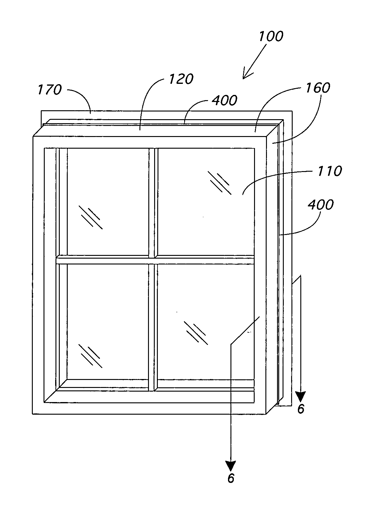
[0031] The first such technique is shown in FIG. 5. There a standard window 100 with a nailing flange 170 has been fitted with a gasket 400 around its circumference. This gasket 400 can be placed on each of the four peripheral faces 160 of the window frame 120, and is positioned between the nailing flange 170 and the interior surface of the window 100. While installing the gasket 400 around all four faces 160 of the window 100 is preferred, it is well within the scope of the present invention to install the ...


PUM


Abstract

A method and device are presented that creates a channel adjacent a nailing flange of a window in between the window and the rough opening that receives the window. The channel is created by establishing a barrier that prevents foam insulation inserted into the space between the window and the rough opening from reaching the nailing flange. The channel then ensures proper drainage of water that enters the window cavity down to the window sill. A gasket is presented that can be attached to the window or the rough opening to create the barrier. Alternatively, a disintegrating object or a wicking object can be used to impede the flow of insulation foam and to create the appropriate channel. The present invention is equally applicable to doors or other framed objects received into the exterior shell of a building.

Description

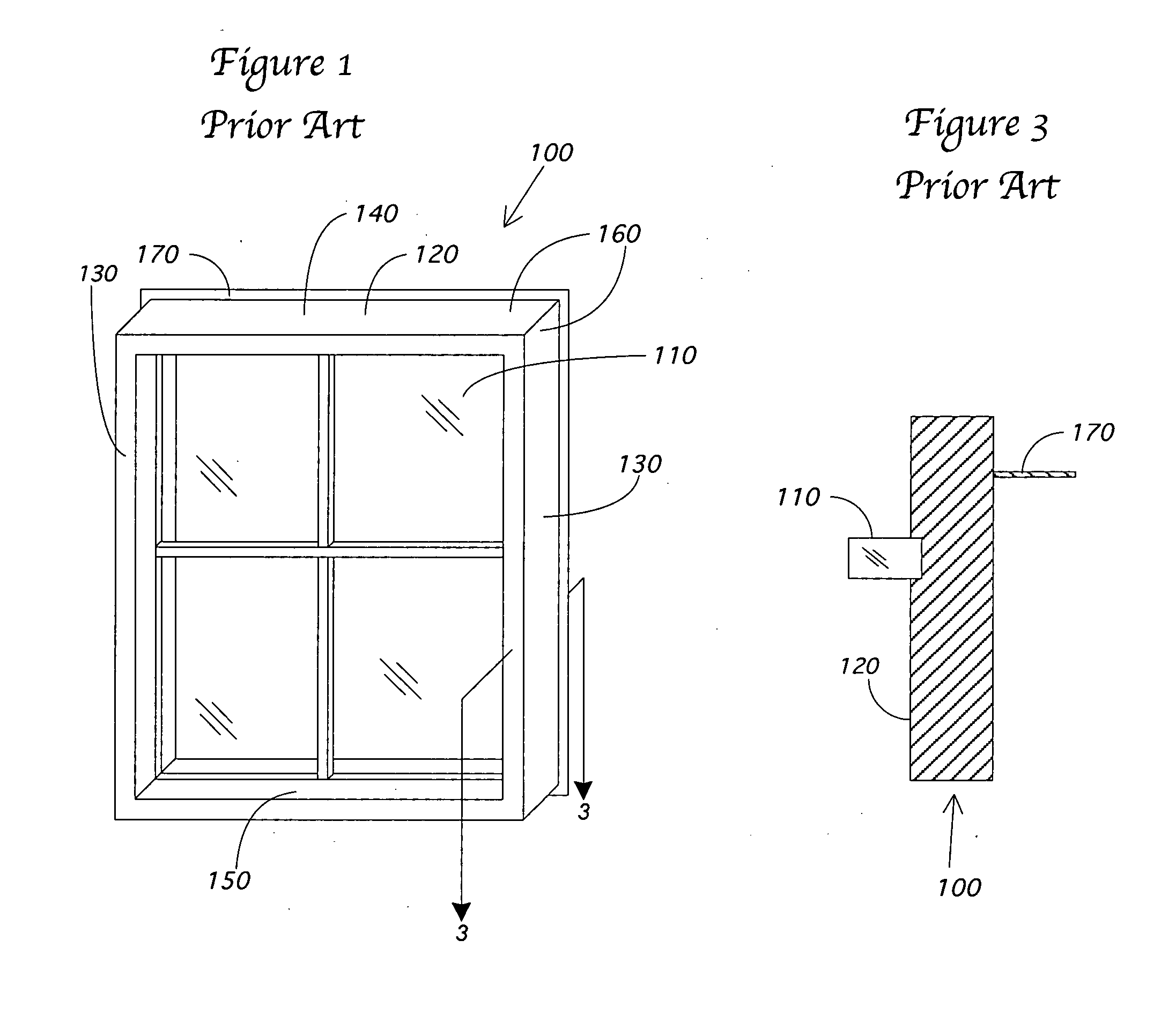
PRIORITY [0001] This application claims the benefit of U.S. Provisional Application No. 60 / 619,343, filed on Oct. 15, 2004.FIELD OF THE INVENTION [0002] The present invention relates to the field of building construction. More particularly, the present invention provides a method and apparatus that prevents water intrusion into the walls of the building around a window, door, or other framed object. BACKGROUND OF THE INVENTION [0003] A typical window 100 of the prior art is shown in FIG. 1. The window 100 may include one or more panes of glass 110, which may be embedded in a single sash, or in an upper and lower sash such as in a double-hung window. The sash is secured in a frame 120, which consists of two side jambs 130, a top jamb 140, and a sill 150. The window frame 120 is typically made from wood, vinyl, aluminum, or fiberglass, but may be made from any durable, rigid material. [0004] Typically, a window is installed into a rough opening 200 in a house or building, as shown in ...

Claims


Application Information

Patent Timeline
IPC IPC(8): E04D13/14
CPCE06B1/58E06B2001/628
Inventor BREN, THOMAS
Owner T STOP PROD LLC
Learn More