Spray pattern characterization and monitoring method and system

a spray pattern and monitoring method technology, applied in the field of spray pattern characterization, can solve the problems of inability to perform detailed evaluation of location, size and type of spray pattern asymmetries, inability to provide information on the location, size or type, and inability to achieve good repeatability, etc., to achieve the effect of identifying problems

Active Publication Date: 2006-04-20
IOOS LLC
View PDF12 Cites 11 Cited by
  • Summary
  • Abstract
  • Description
  • Claims
  • Application Information

AI Technical Summary

Benefits of technology

[0021] It is a further object to provide a method and system to readily identify problems by monitoring location, quantity and size of asymmetries called errors within a spray pattern during operation, as governing parameters change. The obtained error information resulting from deviations between spray pattern and reference pattern may be used for controlling one or more operating parameters such as spray position, atomizing pressure, and spraying cycle to prevent among others inhomogeneous coatings due to atomizer built up or a incorrect position in relation to a spray target.

Problems solved by technology

The P.I. and the S.U.I. are a measure for the overall distribution of the spray pattern, but they don't provide information on the location, size or type of asymmetries within the spray pattern.
Because manual procedures depend on the judgment of an operator, good repeatability is difficult, if not impossible, to achieve.
In addition, a detailed evaluation of location, size, and type of asymmetries within the spray pattern cannot be performed.
In the prior art, characteristics of a spray pattern are not sufficiently quantitatively characterized.

Method used


Image

  • Spray pattern characterization and monitoring method and system
  • Spray pattern characterization and monitoring method and system
  • Spray pattern characterization and monitoring method and system

Examples


Embodiment Construction

[0064] While the invention will be described in connection with certain embodiments, it will be understood that the invention is not limited to these embodiments. On the contrary, the invention includes all alternatives, modifications and equivalents as may be included within the spirit and scope of the present invention. Details in the Specification and Drawings are provided to understand the inventive principles and embodiments described herein, to the extent that would be needed by one skilled in the art to implement those principles and embodiments in particular applications that are covered by the scope of the claims.

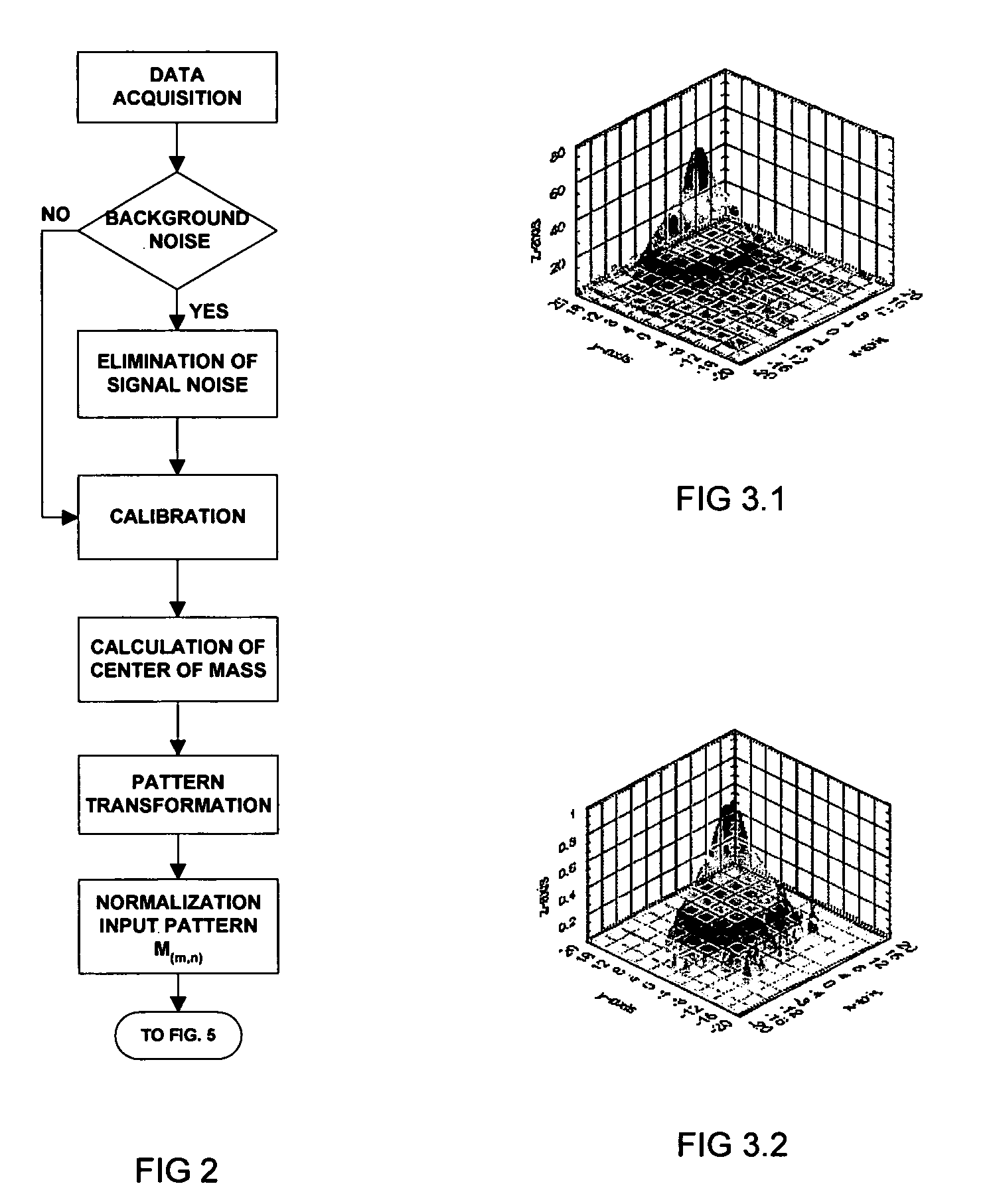
[0065] A detailed evaluation of a spray pattern, also called the input pattern, is achieved by comparing the input pattern with a reference pattern obtained through an empirical or mathematical approach. The input pattern may be comprised in a two-dimensional array, such as an array with a Cartesian or Polar coordinate system.

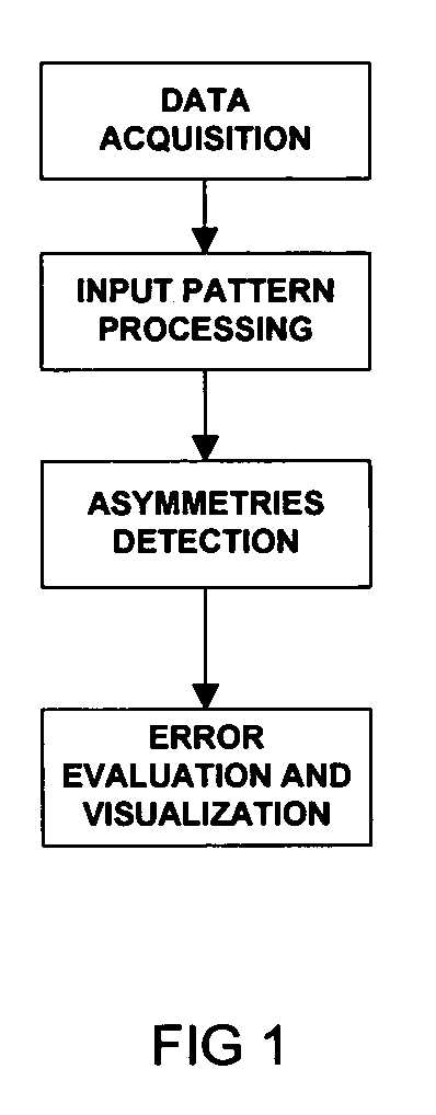
[0066] Referring to FIG. 1, an overvi...


PUM


Abstract

The purpose of the invention is to provide a method to characterize a spray pattern by detecting and quantifying asymmetries resulting in detailed information on location, size, and type of asymmetries within the spray pattern, which are important for spray characterization comparability and classification. A system is provided for in-situ monitoring of the spray characteristics.

Description

CROSS-REFERENCE TO RELATED APPLICATIONS [0001] This Application relates to and claims priority from commonly owned U.S. Provisional Application Ser. No. 60 / 615,169, filed on Oct. 1, 2004, which is incorporated herein by reference.FEDERALLY SPONSORED RESEARCH [0002] Not Applicable SEQUENCE LISTING OR PROGRAM [0003] Not Applicable BACKGROUND OF THE INVENTION [0004] 1. Field of Invention [0005] This invention relates generally to the field of spray pattern characterization and performs measurements of spatial particle distributions within a spray, which can be used to monitor a spraying process. [0006] 2. Background of the Invention [0007] Sprays are associated with, among others, paint spraying, tablet and implant coating, aerosols for inhalation therapy, and fuel injectors. Since the uniformity and symmetry of the spray pattern is a crucial parameter in most applications, it is important to obtain detailed information on spray characteristics. Such information can be used to detect q...

Claims


Application Information

Patent Timeline
Patent Type & Authority Applications(United States)
IPC IPC(8): G01M1/00
CPCB05B12/08B05B12/082
Inventor SCHEER, INGO WERNER
Owner IOOS LLC
Why Eureka
Try Eureka