Personal respirator

a respirator and personal technology, applied in the field of personal respirators, can solve the problems of hammering the capabilities and safety of the wearer, affecting the respirator is also hot and heavy to wear, so as to avoid the effect of wear and tear, and improve the safety of the operator

a respirator and personal technology, applied in the field of personal respirators, can solve the problems of hammering the capabilities and safety of the wearer, affecting the respirator is also hot and heavy to wear, so as to avoid the effect of wear and tear, and improve the safety of the operator

US20060081249A1Inactive Publication Date: 2006-04-20DUXBURY JAMES N

Image

  • Personal respirator
  • Personal respirator
  • Personal respirator

Examples


Embodiment Construction

)

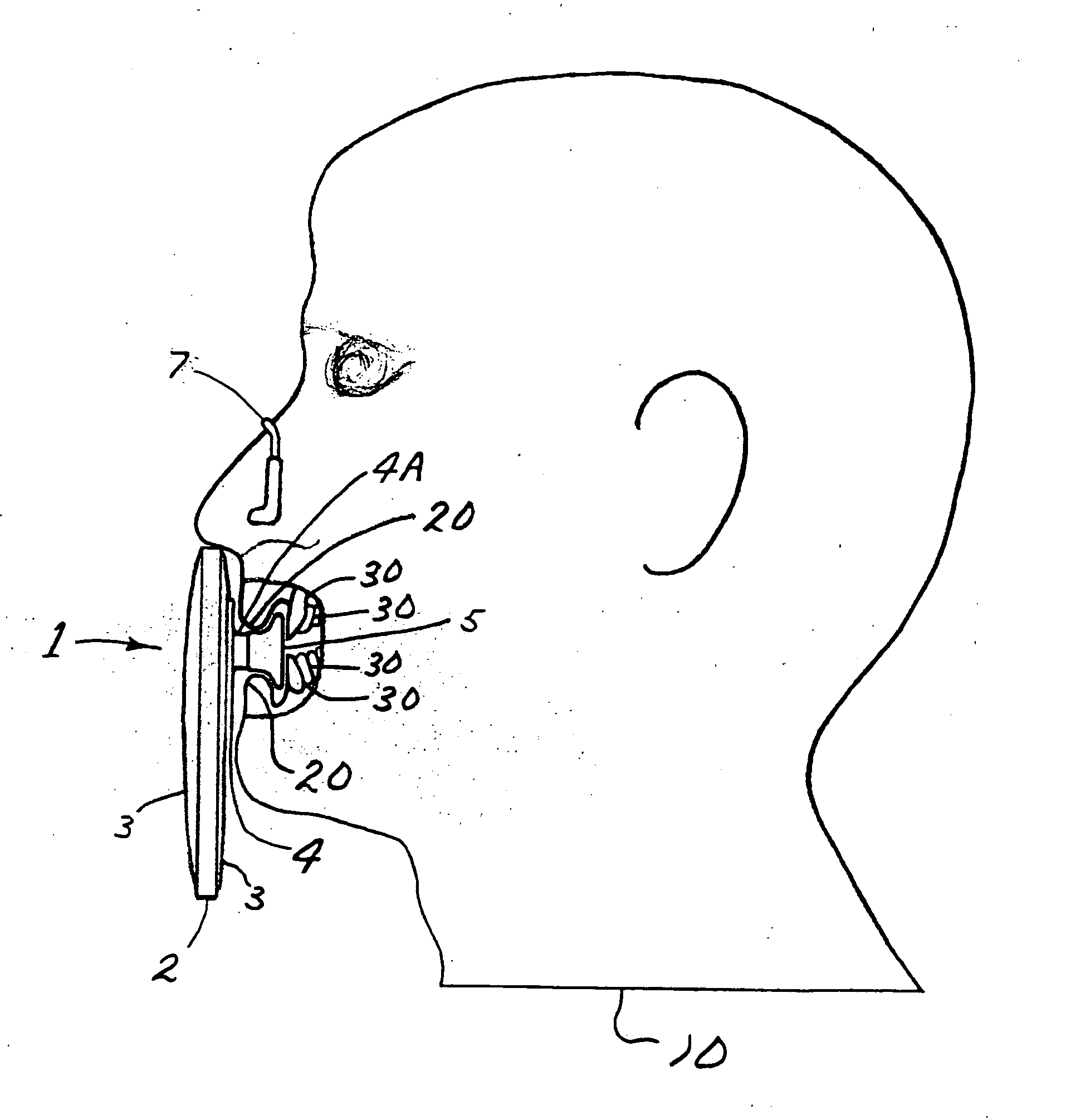
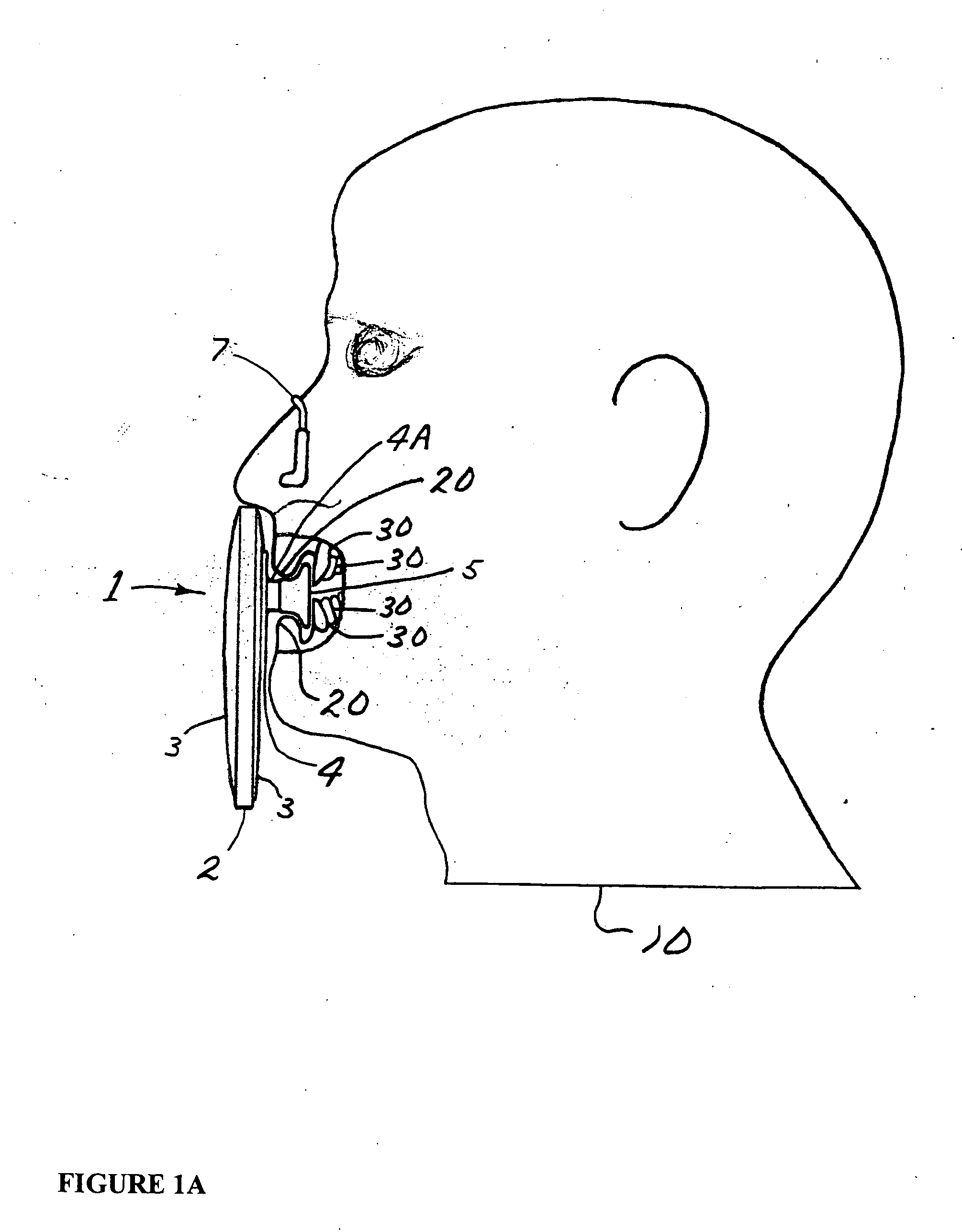
[0015] Referring to FIG. 1, a personal respiratory protection device is designated by the numeral 1. Device 1 is simply installed by placing mouthpiece 5 in the mouth and the nose clip 7 on the nose.

[0016] The mouthpiece is designed to interconnect the device 1 to the user. While this mouthpiece 5 can be of many forms, in the embodiment shown, it is substantially an oval flange having its longitudinal axis substantially in line with the longitudinal axis of the user's mouth (i.e., horizontally between the lips).

[0017] Preferably, the mouthpiece 5 is made of a soft, food grade type material, like silicone, shaped so that when inserted into the mouth between the lips, anterior and adjacent to the teeth, the wearer's lips press down on the air tube 4 (includes tube parts 4 and 4A), (see FIG. 1A) providing a seal, support, and an airway from mouthpiece 5 to the filter plenum 2. This configuration allows the mouth to close and function normally. With the mouth closed, the swallowing p...


PUM


Abstract

This Personal Respirator is a respiratory protection air-purifying device that minimizes the area required in front of the face, especially around the mouth area, by locating the very lightweight filter and plenum close to the head, connected by a airway tube forming a complete unit with the mouthpiece in the mouth, supported by the mouth. The airway tube and the filter plenum are both of minimal internal area and close to the mouthpiece, thus minimizing the internal volume of used air, residual nitrogen, and making the outside dimensions small enough to be compatible with most safety equipment. The respirator requires no straps and is preferably provided with a small tether to the nose clip and is worn in front of the head with the mouthpiece inserted into the mouth, the filter then supported by the mouth, and the nose clip secured on the nose.

Description

[0001] This is a non-provisional of provisional application Ser. No. 60 / 395,266, filed Jul. 15, 2002, the contents of which are incorporated herein in their entirety.BACKGROUND OF INVENTION [0002] Personal respiratory protection has been recommended and required by both government and industry for many years. Studies have been made, standards set, and filtration developed to enable a worker to function in contaminated air with relative safety. However, due to the discomfort, cost, and restrictiveness of the respirator facemask, respirators are only worn when absolutely necessary and in many cases, hamper the capabilities and safety of the wearer. Respirators are also hot and heavy to wear, exerting pressure on sensitive areas of the face. They are impossible to wear properly with facial hair, sensitive skin, deep scars, or facial deformities. Respirators protrude in front of the face, limiting visibility and trapping large amounts of exhaled air that condenses on the face. The exces...

Claims


Application Information

Patent Timeline
20 Apr 2006
Publication
US20060081249A1
IPC
A62B23/02; A62B7/10; A62B23/06
CPC
A62B23/06
Inventors
DUXBURY, JAMES N.