Side tank design

a side tank and side tank technology, applied in the direction of tubular elements, lighting and heating apparatus, stationary conduit assemblies, etc., can solve the problems of affecting the assembly of the unit, affecting the installation of the unit, and not providing adjustment in the mounting points

Active Publication Date: 2006-04-20
LEGEND BRANDS INC
View PDF17 Cites 35 Cited by
  • Summary
  • Abstract
  • Description
  • Claims
  • Application Information

AI Technical Summary

Problems solved by technology

The direct-fit replacement units, however, do not provide adjustability in the mounting points.
Thus, any manufacturing misalignments would greatly hinder the assembly of the unit.
Similarly, attempting to modify the engine can result in clearance problems when assembling necessary cooling components.
One problem with this type of mounting system is that it does not provide means for easily adjusting the mounting points after the bracket has been welded to the unit body.
Unfortunately, the ties have a tendency to damage the thin cooling fins and to subsequently reduce the efficiency of the cooling device.
Nevertheless, neither alternative option provides adjustability after an initial mounting point has been fixed.
Thus, one problem associated with current cooling systems is that they do not maximize the available cooling space.

Method used


Image

  • Side tank design
  • Side tank design
  • Side tank design

Examples


Embodiment Construction

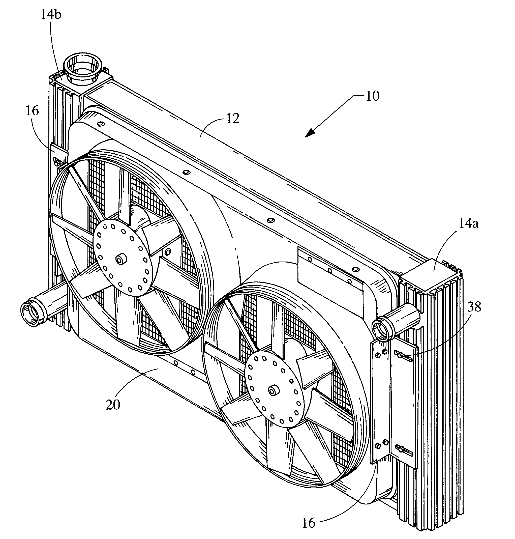
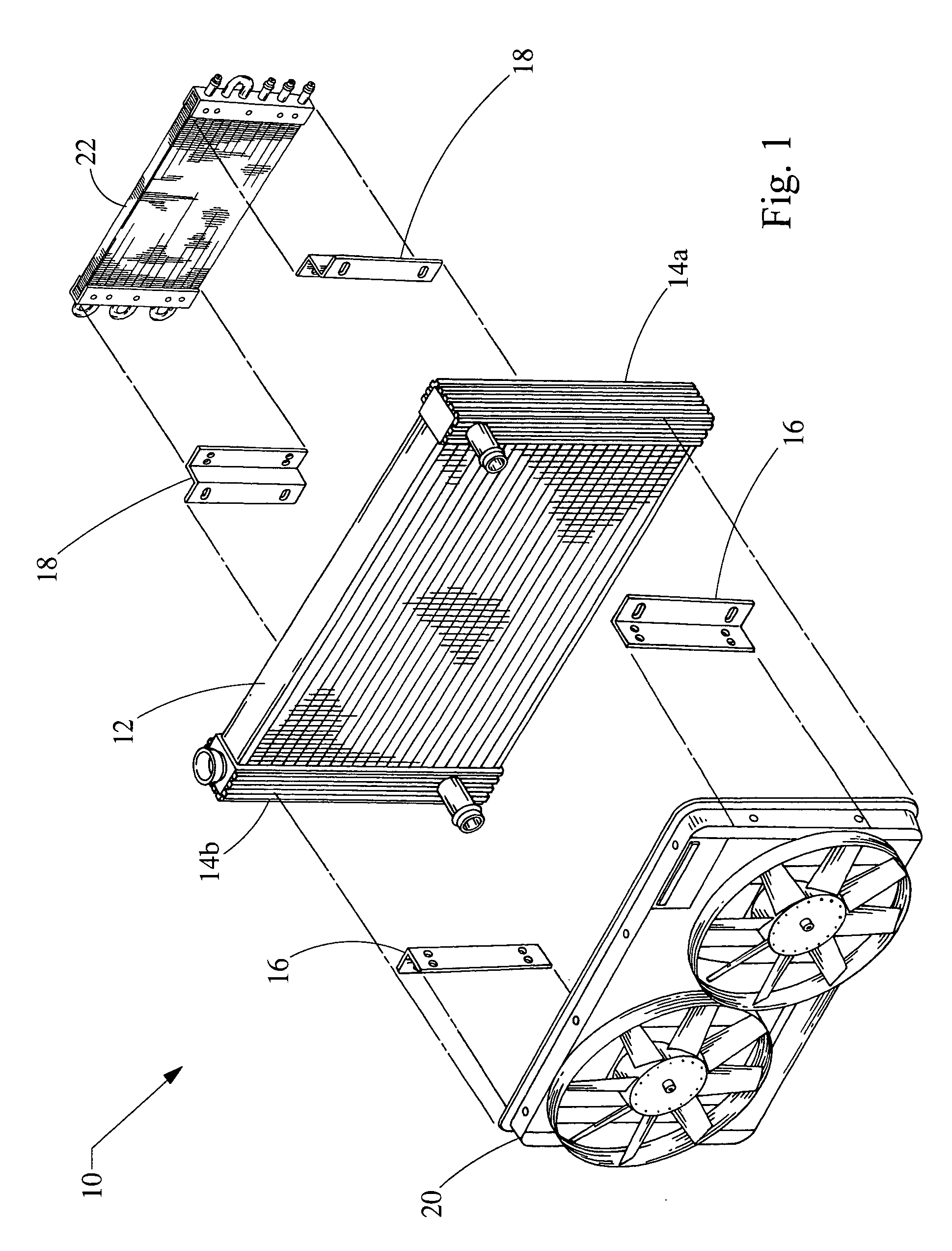
[0022] Referring to FIG. 1, a cooling system 10 includes a main cooling device 12, sometimes referred to as the core, an inlet side tank 14a, and an outlet side tank 14b. The cooling system 10 is generally used in internal combustion engines of moving or stationary vehicles, such as automobiles, motorcycles, boats, and power-generators. The engine is also known as a reciprocating engine, and it can be fueled by gasoline, diesel, propane, or any other combustible material.

[0023] The cooling system 10 can be provided in either a cross-flow configuration (shown in FIG. 1) or in a down-flow configuration (shown in FIG. 8). For example, a cooling system 10 can be a radiator, an engine oil cooler, a transmission oil cooler, an inner cooler, a charge air cooler, a power steering fluid core, a hydraulic pump fluid cooling core, a fuel cooler, or a condenser. Using additional brackets 16, 18 other accessories, such as a cooling fan 20 and an oil cooler 22, can be mounted to the cooling syst...


PUM


Abstract

A cooling system for a reciprocating engine includes a main cooling device and a side tank. The main cooling device includes at least one heat dissipation tube that contains an internal fluid for transporting excess heat developed by a reciprocating engine. The side tank is attached to the main cooling device and includes a plurality of exterior fins for dissipating heat to cool airflow. The exterior fins form an adjustable mounting location.

Description

FIELD OF THE INVENTION [0001] The present invention relates generally to a cooling system for a reciprocating engine, and in particular to a radiator core having a side tank that provides enhanced heat dissipation and an adjustable mounting system. BACKGROUND OF THE INVENTION [0002] Cooling systems such as radiators, engine oil coolers, inner coolers, and transmission oil coolers, have always been an essential component of internal combustion engines, such as engines used in automobiles and boats. The cooling systems are sold both as original equipment and as aftermarket replacements or upgrades. When the cooling systems are sold in the aftermarket, they are sold as either direct-fit replacement units, which are tailored to a particular vehicle, or as universal-fit replacement units, which require custom mounting. [0003] Direct-fit replacement units have existing fixed mounting points that align to the mounting points of a vehicle, which can be located on an engine of the vehicle. T...

Claims


Application Information

Patent Timeline
Patent Type & Authority Applications(United States)
IPC IPC(8): F28F9/02
CPCF28D1/0435F28F1/16F28F9/002F28F9/02F28F9/0224F28F2275/14F28F2009/0292F28F2255/16
Inventor CHISSUS, LISA L.
Owner LEGEND BRANDS INC
Why Eureka
Try Eureka