Single, multiplexed operational amplifier to improve current matching between channels

an operational amplifier and channel technology, applied in the direction of electric variable regulation, process and machine control, instruments, etc., can solve the problems of unavoidable manufacturing variations, random offset within each amplifier is more difficult to correct, and often the main contributor to mismatch, so as to reduce the refresh frequency of current sinks, eliminate the contribution of amplifier offset to current mismatch, and reduce power consumption

Inactive Publication Date: 2006-04-20
ADVANCED ANALOGIC TECHNOLOGIES INCORPORATED
View PDF10 Cites 22 Cited by
  • Summary
  • Abstract
  • Description
  • Claims
  • Application Information

AI Technical Summary

Benefits of technology

[0004] Two multiplexors are used to select one current sink at a time. When selected, one multiplexor connects the feedback sense node of the selected current sink to one of the inputs of the operational amplifier. The second multiplexor connects the output of the operational amplifier to the MOSFET gate of the selected current sink. The operational amplifier compares the feedback sense node voltage to a set voltage Vset and causes the selected current sink to draw a regulated current proportional to Vset. Each current source is selected in sequence. When non-selected, gate capacitance causes the disconnected MOSFETS to maintain their regulated currents. By sequencing through the different current sinks at a predetermined rate, regulation of each current sink is maintained. Additional capacitance can be added at the gate of each MOSFET to decrease the refresh frequency of the current sinks.
[0005] The use of a single amplifier multiplexed between current sinks eliminates the contribution of amplifier offset to current mismatch. This topology also reduces power consumption by minimizing the number of active devices.

Problems solved by technology

Unfortunately, mismatches inevitably result because manufacturing variations are unavoidable.
Though mismatch between sense-resistors can be minimized with careful layout, random offset within each amplifier is more difficult to correct and can contribute directly to mismatch between channel currents.
In fact, random offset is often the main contributor to mismatch—particularly where R is small since I=Vset / R+Vos / R.

Method used


Image

  • Single, multiplexed operational amplifier to improve current matching between channels
  • Single, multiplexed operational amplifier to improve current matching between channels
  • Single, multiplexed operational amplifier to improve current matching between channels

Examples


Embodiment Construction

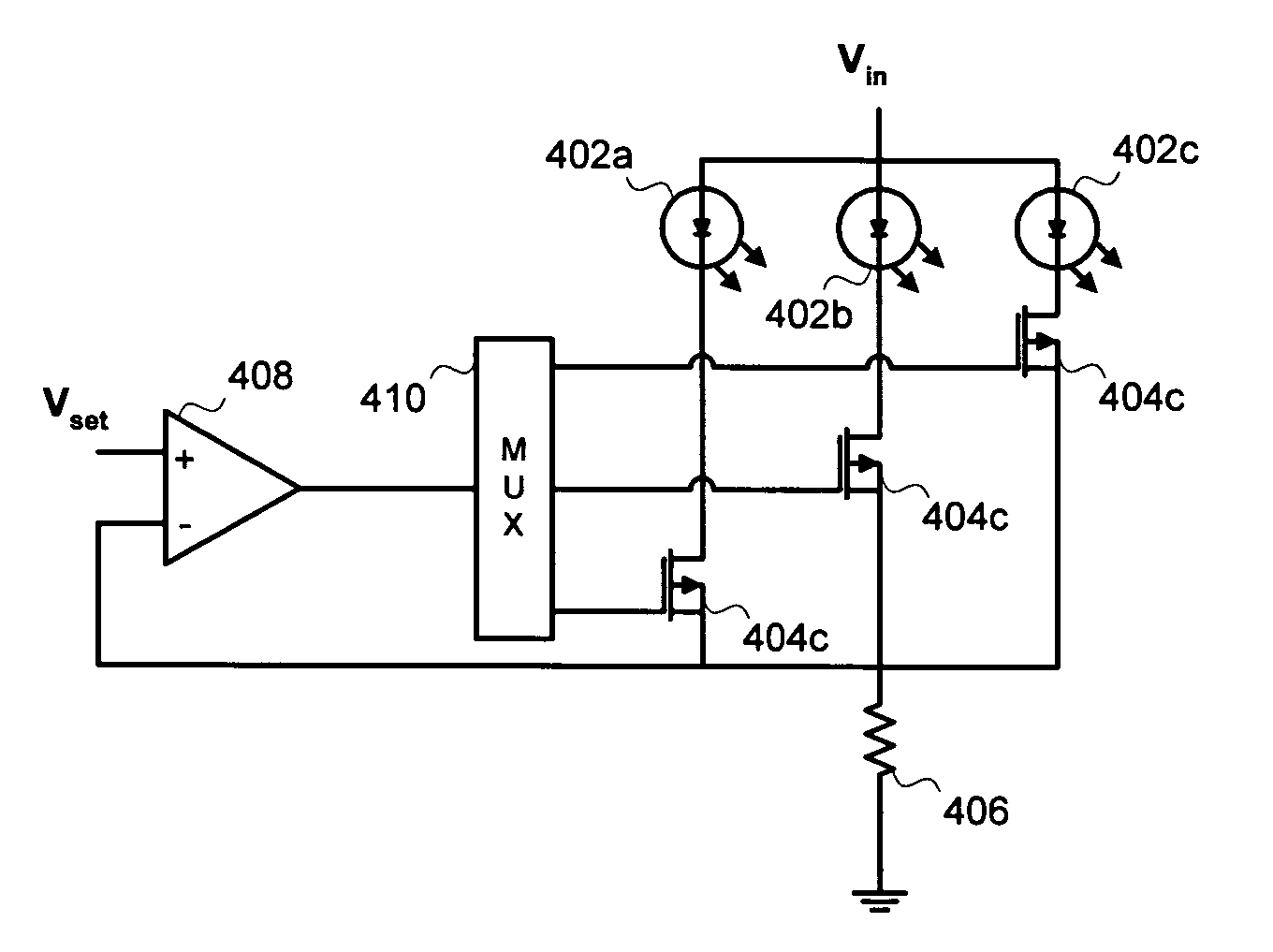
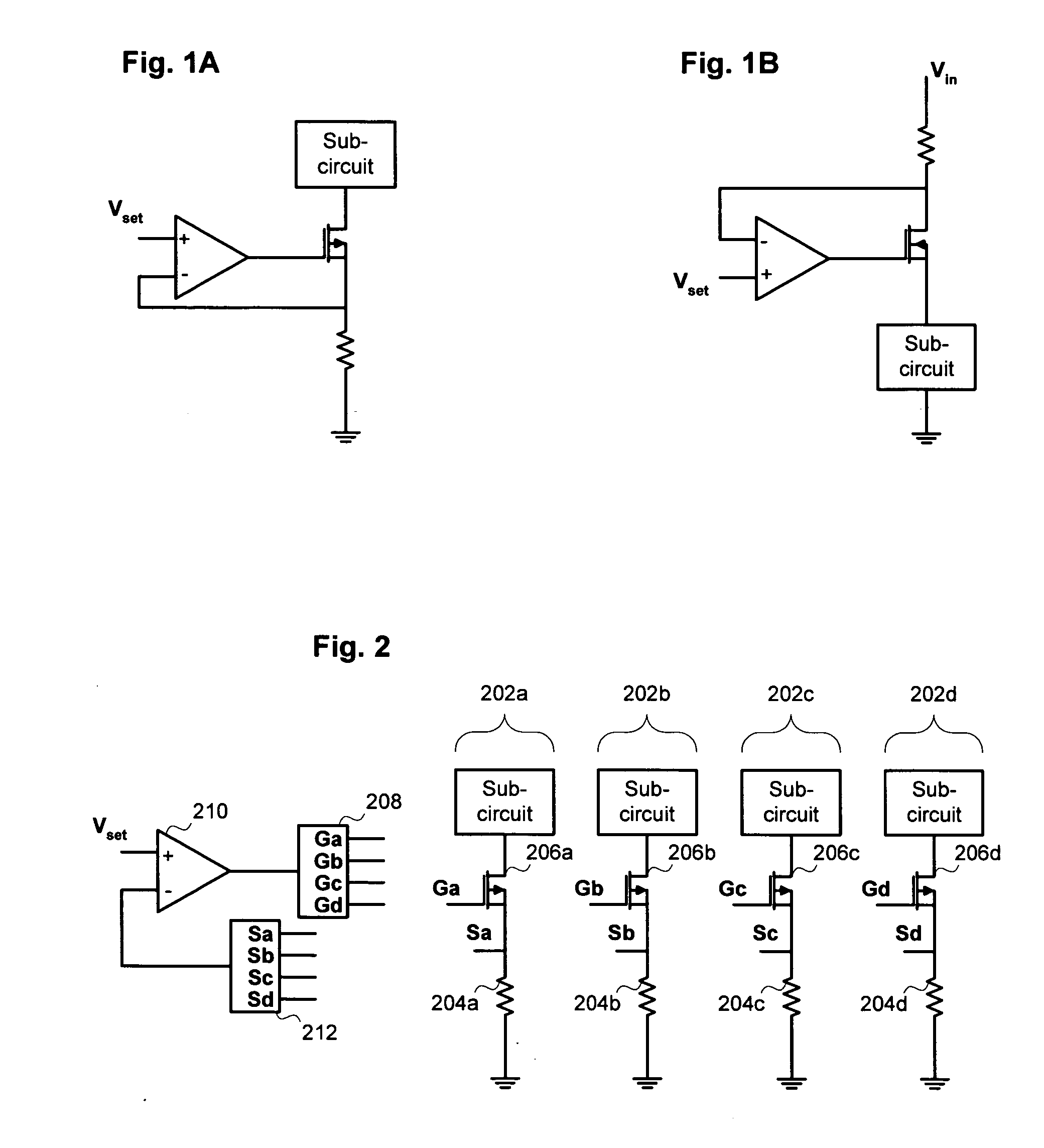
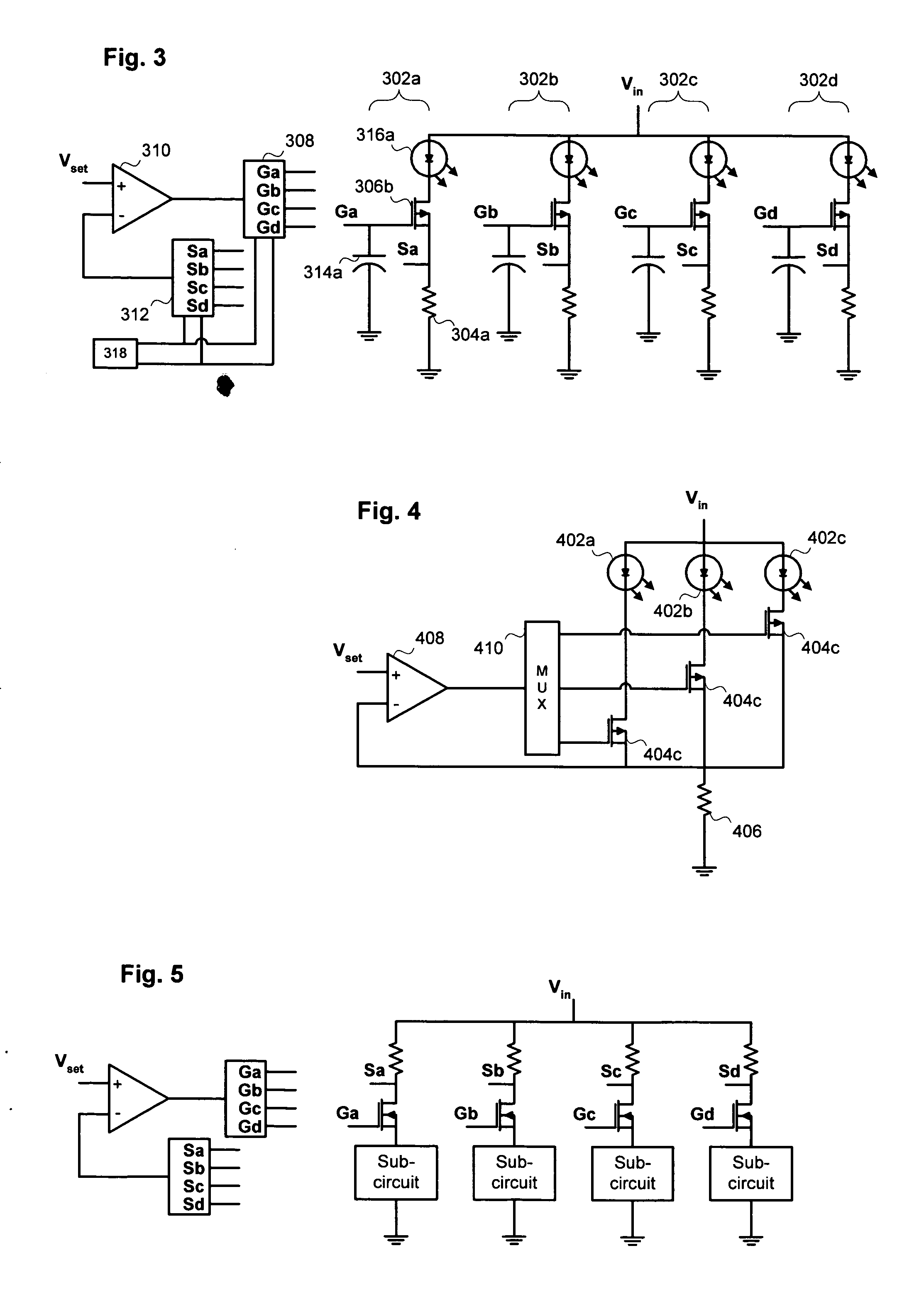
[0014] The present invention includes a multi-channel current sink. As shown in FIG. 2, a representative implementation of the multi-channel current sink includes a series of four channels, labeled 202a through 202d. The number of channels 202 is entirely implementation dependent and can be more or less than the four shown. Each channel 202 includes a sense resistor (labeled 204a through 204d) and a MOSFET (labeled 206a through 206d). As shown in FIG. 2, a first multiplexor 208 is used to connect the output of an operational amplifier 210 to the gate of one MOSFET 206. At the same time, a second multiplexor 212 connects a feedback sense node (the voltage over the corresponding resistor 204) of the same channel 202 to the negative input of the amplifier 210.

[0015] Multiplexor 208 and multiplexor 212 are controlled so that each channel is selected in sequence. When selected, a particular channel 202 is connected to the amplifier 210 and behaves exactly as the circuit in FIG. 1A. This...


PUM


Abstract

A multi-channel current regulator includes two or more channels, each channel acting as a current source or sink for a respective load. Each channel regulates its load current so that the load current is proportional to an input voltage supplied to the channel. Each channel also generates a feedback voltage that is proportional to the load current of the channel. The current regulator also includes an operational amplifier. The amplifier is connected, using two multiplexors to drive one channel at a time. Each channel is selected in a rotating sequence for connection to the amplifier. Internal gate capacitance maintains each channel not connected to the amplifier at its previously set load current.

Description

BACKGROUND OF THE INVENTION [0001] Current sources and current sinks are commonly used to provide regulated currents in circuits of all types. As shown in FIG. 1A, a current sink can be constructed as a combination of a sense resistor, a MOSFET and an operational amplifier. The operational amplifier adjusts the voltage at the gate of the MOSFET to minimize the voltage difference between the inputs of the op amp. In a perfect system, the voltage at the source of the MOSFET, Vs, equals the voltage on the positive terminal of the amplifier, Vset, and the current is given by I=Vset / R. Figure 1B shows a current source constructed using a similar combination of components. [0002] Duplication of the current sink or source structure can produce additional channels with nearly matched currents when referred to the same set voltage, Vset. For the currents in each channel to be equal, all duplicated elements must exactly match in value and characteristics. Unfortunately, mismatches inevitably ...

Claims


Application Information

Patent Timeline
Patent Type & Authority Applications(United States)
IPC IPC(8): G05F1/10
CPCG05F1/577
Inventor D'ANGELO, KEVIN P.FERRARIO, BRUNODEMPSEY, DAN
Owner ADVANCED ANALOGIC TECHNOLOGIES INCORPORATED
Why Eureka
Try Eureka