Continuous inkjet printer having adjustable drop placement

Inactive Publication Date: 2006-04-20
EASTMAN KODAK CO
View PDF28 Cites 7 Cited by
  • Summary
  • Abstract
  • Description
  • Claims
  • Application Information

AI Technical Summary

Benefits of technology

[0043] One advantage of the present invention that it provides a subdivided interval for droplet formation, allowing a number of flexible timing arrangements for droplet delivery from each individual inkjet nozzle and enabling a compact means of representing and controlling such timing arrangements. Another advantage of the present invention is that it provides precision printing droplet positioning in the fast scan direction. The present invention is also usable in conjunction with other printed drop positioning solutions, particularly those applicable to slow scan positioning. An additional advantage of the present invention is that

Problems solved by technology

However, continuous ink jet printing devices can be more complex than drop-on-demand printers, since each color printed requires an individual droplet formation, deflection, and capturing system.
One well known problem with any type of inkjet printer, whether drop-on-demand or continuous flow, relates to precision of dot positioning.
If the placement of the droplets is incorrect and/or their placement cannot be controlled to achieve the placements desired within each pixel area, image artifacts may occur, particularly if similar types of deviations from desired locations repeat in adjacent pixel areas.
Incorrect placement of droplets may occur due to manufacturing variations between nozzles or to dirt or debris in or near some nozzles.
Slight errors in trajectory result in corresponding placement errors for printed drops.
Another possible error source for dot placement is response time, which can be slightly different between nozzles in an array, resulting in displacement errors in the fast scan direction.
For the most part, these minor differences result in error distances that are some fraction of a pixel dimension.
However, as is well known in the imaging arts, undesirable banding effects can be the result of a repeated pixel positioning error due to the printhead or its support mechanism.
Manufacturers of inkjet systems r

Method used


Image

  • Continuous inkjet printer having adjustable drop placement
  • Continuous inkjet printer having adjustable drop placement
  • Continuous inkjet printer having adjustable drop placement

Examples


Example

[0060] The present description is directed in particular to elements forming part of, or cooperating more directly with, apparatus in accordance with the invention. It is to be understood that elements not specifically shown or described may take various forms well known to those skilled in the art.

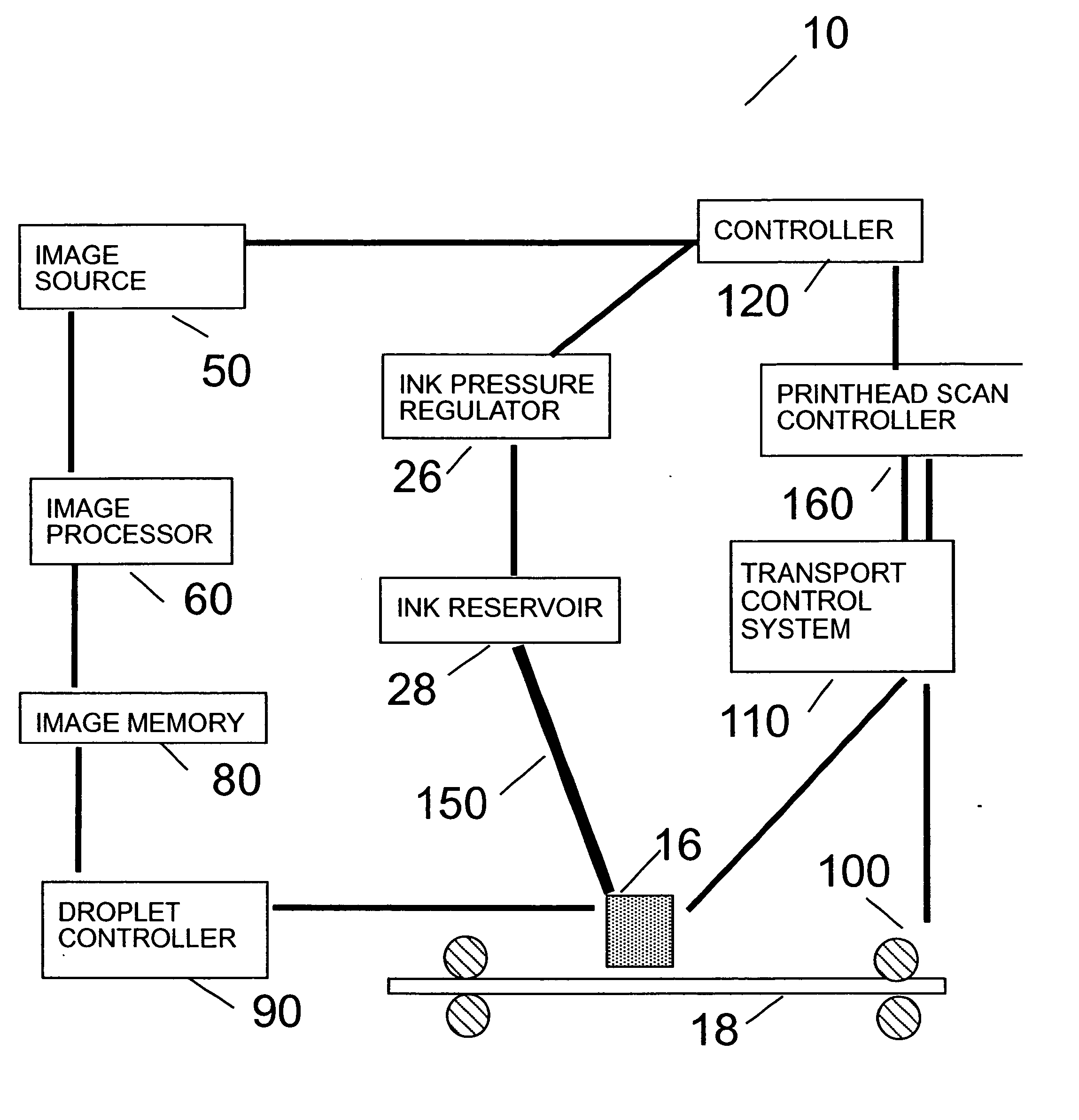
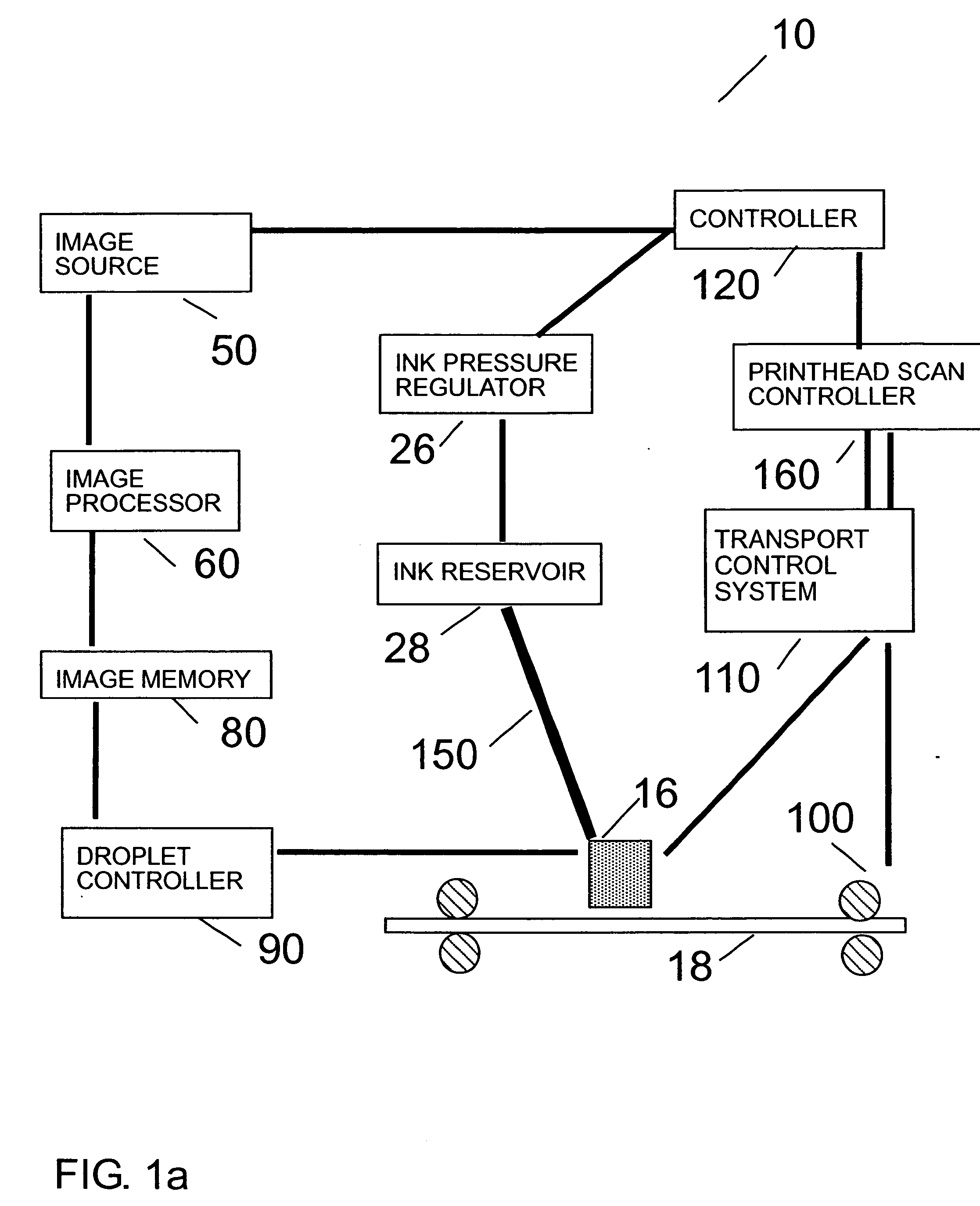
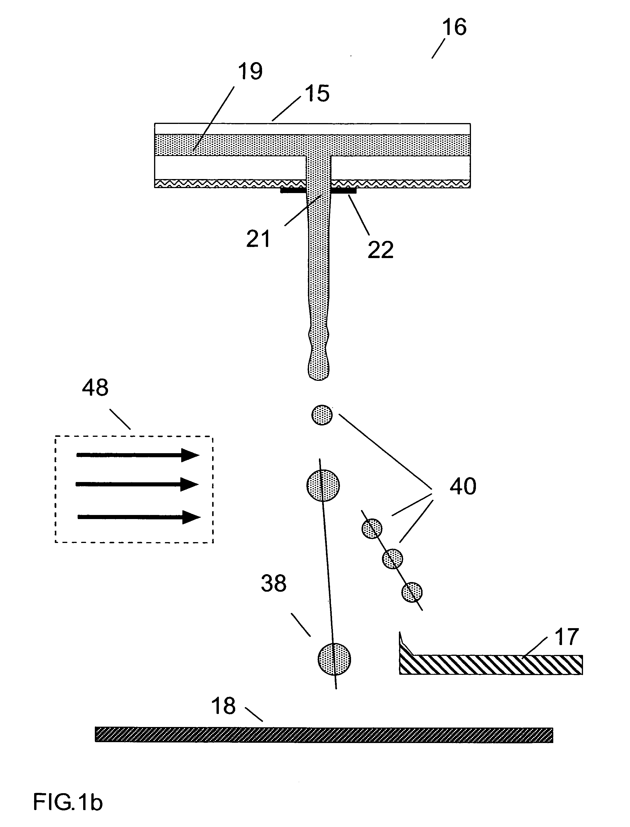
[0061] Referring to FIG. 1a-1b, there is shown an imaging apparatus 10 capable of controlling the trajectory of fluid droplets according to the present invention. Imaging apparatus 10 accepts image data from an image source 50 and processes this data for a print head 16 in an image processor 60. Image processor 60, typically a Raster Image Processor (RIP) or other type of processor, converts the image data to a pixel-mapped page image for printing. During printing operation, a recording medium 18 is moved relative to print head 16 by means of a plurality of transport rollers 100, which are electronically controlled by a transport control system 110. A logic controller 120 provides contro...


PUM


Abstract

A method of printing includes associating a pixel area of a recording medium with a nozzle and a time interval during which a fluid drop ejected from the nozzle can impinge the pixel area of the recording medium; dividing the time interval into a plurality of subintervals; grouping some of the plurality of subintervals into blocks; associating one of two labels with each block, the first label defining a printing drop, the second label defining non-printing drops; associating no drop forming pulse between subintervals of each block having the first label; associating a drop forming pulse between each subinterval of each block having the second label; associating a drop forming pulse between other subintervals, the drop forming pulse being between each pair of consecutive blocks; and causing drops to be ejected from the nozzle based on the associated drop forming pulses.

Description

CROSS REFERENCE TO RELATED APPLICATIONS [0001] Reference is made to commonly assigned, U.S. patent application Kodak Docket No. ______ filed concurrently herewith, entitled “SUPPRESSION OF ARTIFACTS IN INKJET PRINTING, in the name of Gilbert A. Hawkins, et al., the disclosure of which is incorporated herein by reference.FIELD OF THE INVENTION [0002] This invention generally relates to digitally controlled printing devices and more particularly relates to a continuous ink jet printhead that integrates multiple nozzles on a single substrate and in which the breakup of a liquid ink stream into printing droplets is caused by a periodic disturbance of the liquid ink stream. BACKGROUND OF THE INVENTION [0003] Ink jet printing has become recognized as a prominent contender in the digitally controlled, electronic printing arena because, e.g., of its non-impact, low-noise characteristics, its use of plain paper and its avoidance of toner transfers and fixing. Ink jet printing mechanisms can ...

Claims


Application Information

Patent Timeline
IPC IPC(8): B41J29/38
CPCB41J2/03B41J2/07B41J2002/022B41J2002/031B41J2002/033
Inventor HAWKINS, GILBERT A.JEANMAIRE, DAVID L.
Owner EASTMAN KODAK CO
Why Eureka
Try Eureka