Angled cone of loudspeaker

a loudspeaker and cone technology, applied in the direction of transducer details, electrical transducers, electrical apparatus, etc., can solve problems such as deteriorating tone quality, and achieve the effect of eliminating any possible deformation or tone quality degradation and improving strength

Inactive Publication Date: 2006-04-20
OHARA HIROSHI
View PDF1 Cites 7 Cited by
  • Summary
  • Abstract
  • Description
  • Claims
  • Application Information

AI Technical Summary

Benefits of technology

[0007] The primary object of the present invention is to provide a cone with bett

Problems solved by technology

Since such a conventional cone has a plane or slightly arcuate surface, hence, it is

Method used


Image

  • Angled cone of loudspeaker
  • Angled cone of loudspeaker
  • Angled cone of loudspeaker

Examples


Embodiment Construction

[0016] As illustrated in FIGS. 3 and 4, a cone of the present invention is prepared by using a variety of cloth, paper, rubber, and the likes, and laying a tailored polygonal chip of any of the mentioned materials in the space between an upper half and a lower half mold, then, pressing the chip with heat to have a desired cone structure obtained.

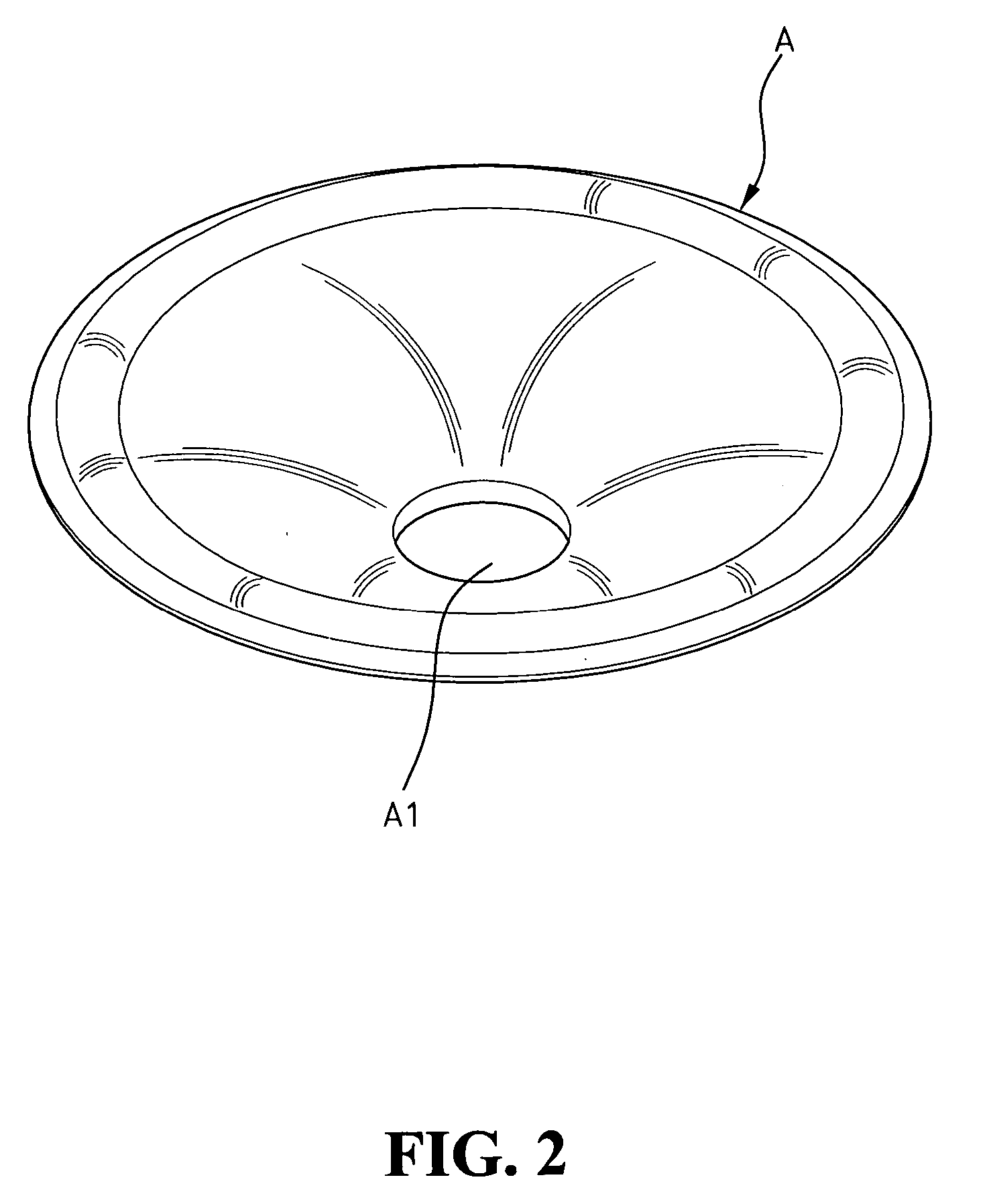
[0017] It is understood that a cone 1 is formed in a pentagonal cone formed with a central through hole 13 for mounting a voice coil. In building the cone 1, a plurality of turning points 11 is formed radially on a peripheral inner surface of the cone to divide it into multiple planes. Also, at least an annular deflective line 12 is formed on a waistline defined above the through hole 13 for further dividing each plane into two. The key point is that there are no conspicuous ridged lines made and shown in any of the intersections of the turning points 11 and the annular defective line 12, such that it is possible to maintain the elasticity ...


PUM


Abstract

An angled cone of loudspeaker is pressed with heat to form a polygonal cone body, in which a plurality of turning points is arranged radially while a deflective line is disposed annually to thereby maintain the proper elasticity and the strength of the cone.

Description

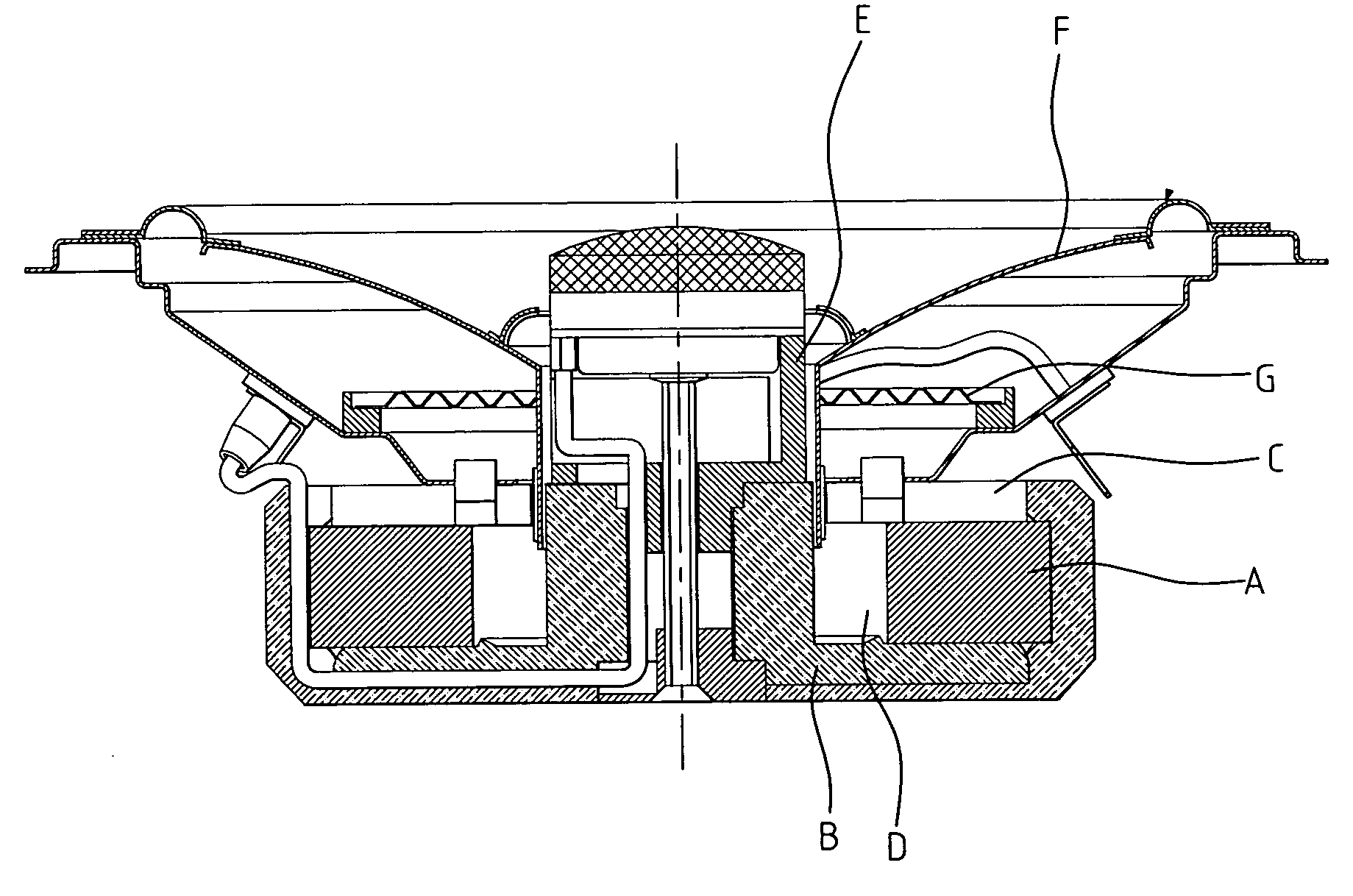
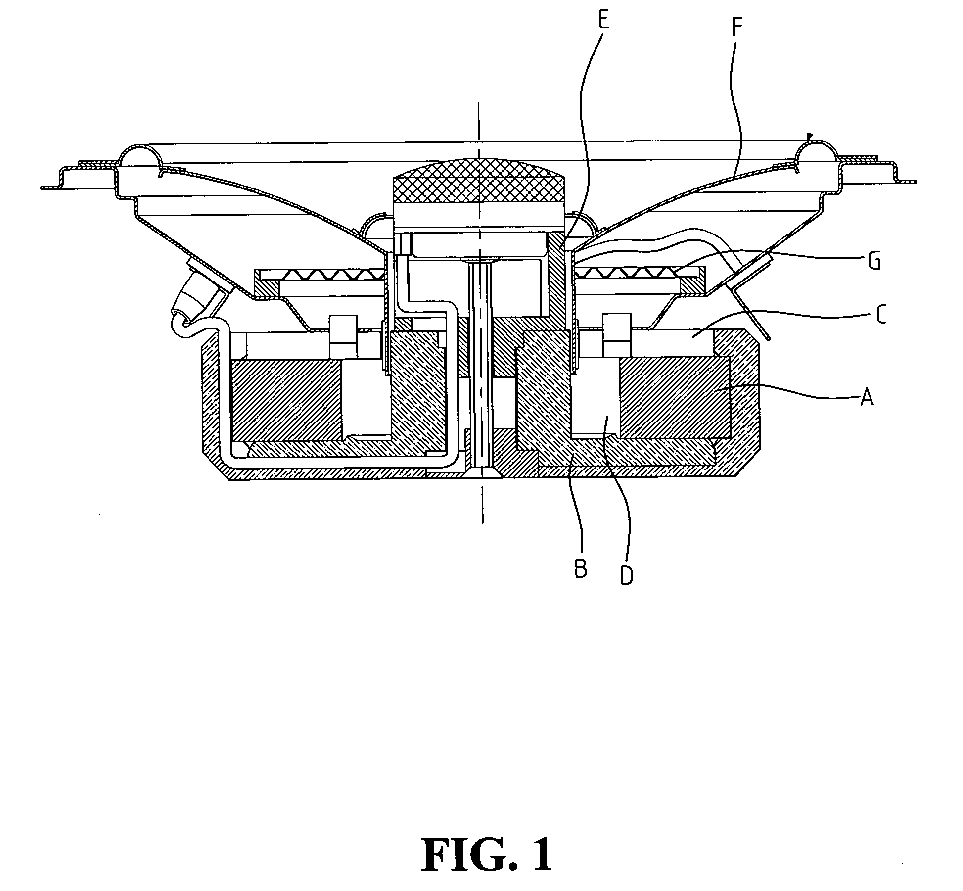
BACKGROUND OF THE INVENTION [0001] 1. Field of the Invention [0002] The present invention relates to a voice-generating acoustic device applied in loudspeakers for displacing air. [0003] 2. The Prior Arts [0004]FIG. 1 shows a typical conventional dynamic structure of loudspeaker, comprising a motive power system, a cone, and a suspension system, in which the motive power system further comprises a magnet A, an electrode piece B, an upper iron C, and a voice coil E. The cone, which is substantially a diaphragm F for displacing air, is usually formed as a conic or semi-spherical acoustic bowl, and the suspension system, which is comprised of a damper G and a suspension edge thereof, is provided for damping the diaphragm F moving in a specified direction. [0005] The working principle of the dynamic loudspeaker is that an electromagnetic field is generated in a direction perpendicular to the magnetic field induced by a permanent magnet of the loudspeaker when a current flows through a v...

Claims


Application Information

Patent Timeline
IPC IPC(8): H04R1/00H04R9/06H04R11/02
CPCH04R7/18
Inventor OHARA, HIROSHI
Owner OHARA HIROSHI
Why Eureka
Try Eureka