Composite dry vacuum pump having roots rotor and screw rotor

screw rotor technology, applied in the direction of machines/engines, liquid fuel engines, positive displacement liquid engines, etc., can solve the problems of increasing the number of components and the cost of assembly, increasing the factors of gas leakage, and increasing the cost of manufacturing a dry vacuum pump. , to achieve the effect of reducing the power requirement and increasing the volum

Active Publication Date: 2006-04-20
LOT VACUUM
View PDF8 Cites 20 Cited by
  • Summary
  • Abstract
  • Description
  • Claims
  • Application Information

AI Technical Summary

Benefits of technology

[0011] Accordingly, it is the first object of the present invention to provide an improved dry vacuum pump in which it is possible to reduce the power requirement and increas

Problems solved by technology

However, in a dry vacuum pump 100 disclosed in U.S. Pat. No. 5,549,463, as a partition wall 108 is formed between a pair of roots rotor 102, 103 and a pair of screw rotor 105, 106, the housing including these elements is divided into several portions, which causes to increase efforts and cost in manufacturing a dry vacuum pump 100.
However, because the conventional dry vacuum pump using afor

Method used


Image

  • Composite dry vacuum pump having roots rotor and screw rotor
  • Composite dry vacuum pump having roots rotor and screw rotor
  • Composite dry vacuum pump having roots rotor and screw rotor

Examples


Embodiment Construction

[0047] The following embodiments are given for the purpose of illustration only and are not intended to limit the scope of this invention.

[0048] Hereinafter, the preferred embodiments according to the present invention will be described with reference to the accompanying drawings. Here, when one element is connected to another element, one element may be not only directly connected to another element but also indirectly connected to another element via another element. Further, irrelative elements are omitted for clarity. Also, like reference numerals refer to like elements throughout.

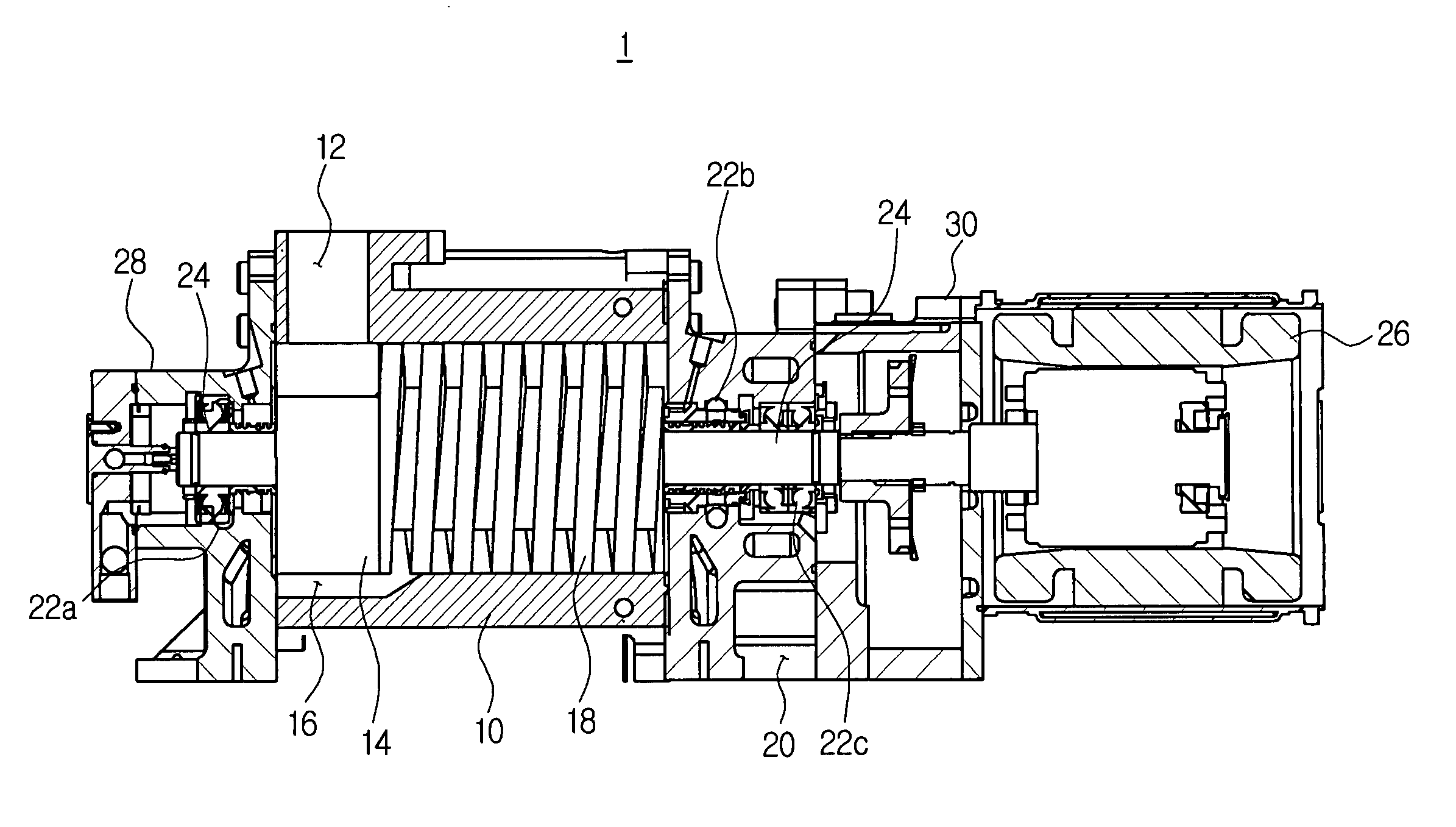
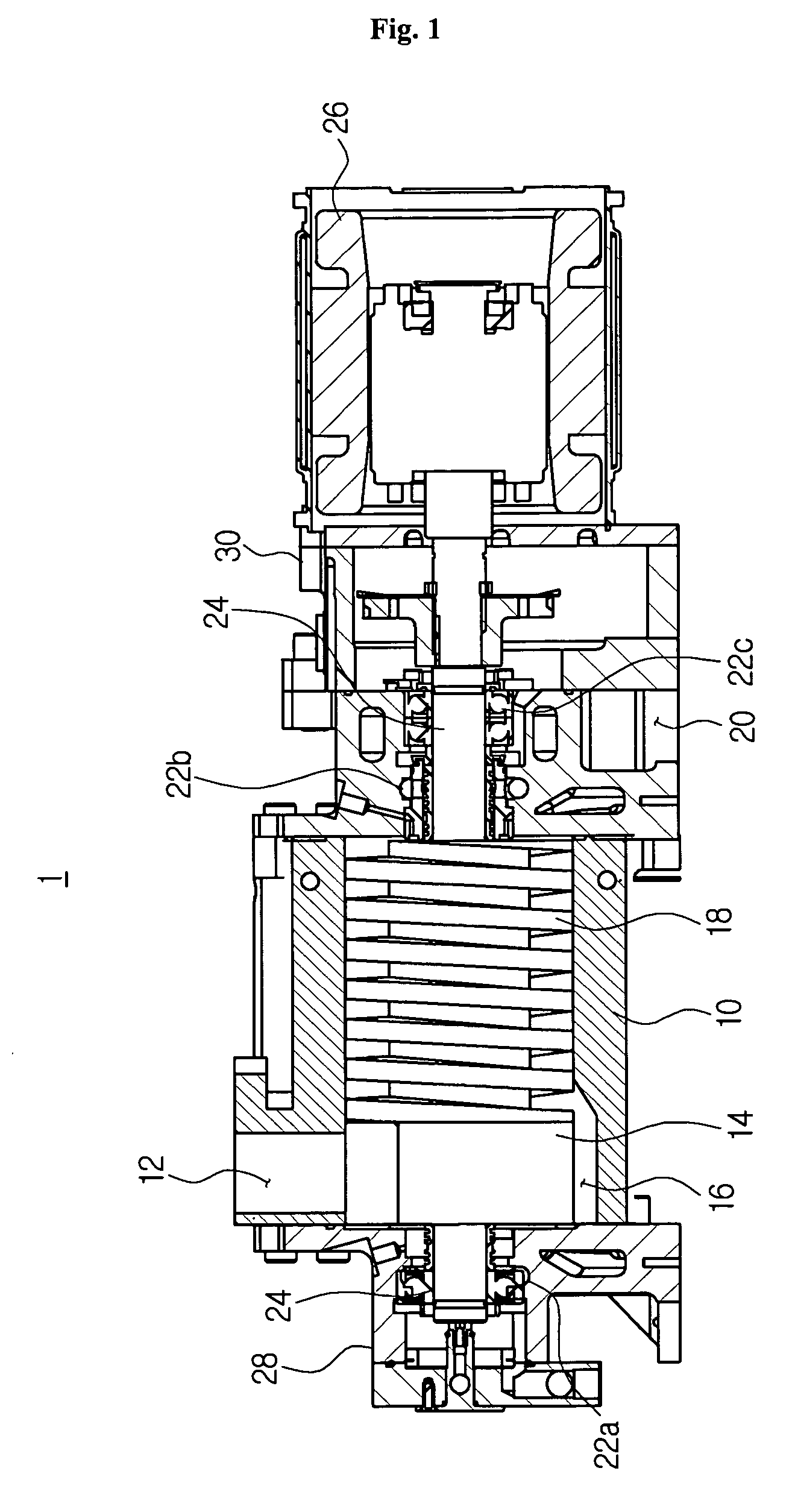
[0049]FIG. 1 is a sectional view showing main parts of a dry vacuum pump according to the first aspect of present invention.

[0050] Referring to FIG. 1, a dry vacuum pump 1 according to the first aspect of the present invention comprises a roots motor 14 on front end side, a driving motor 26, preferably water-cooling driving motor on rear end side, and a screw motor 18 between the roots motor 14 and ...


PUM


Abstract

Disclosed is a dry vacuum pump for evacuating a processing chamber in semiconductor or display manufacturing device, or for evacuating the gaseous substance and/or the byproducts generated in process chamber. The dry vacuum pump does not need a partition wall between a roots rotor and a screw rotor. In the dry vacuum pump, a space is formed on the connecting portion to roots rotor among through the under sides of the roots rotor and the screw rotor to stay the object substance thereon.

Description

CROSS-REFERENCE TO RELATED APPLICATION [0001] This application claims priority to Korean Patent Application Nos. 10-2004-0078422, 10-2004-0078423, and 10-2004-0078431 filed on Oct. 1, 2004. FIELD OF THE INVENTION [0002] The present invention relates to a composite dry vacuum pump for evacuating a process chamber of a semiconductor manufacturing device and a display manufacturing device and the like, or for discharging gaseous substance and / or byproducts generated in the process chamber. BACKGROUND OF THE INVENTION [0003] Generally, a composite dry vacuum pump has been used for evacuating the process chamber a semiconductor manufacturing device and a display manufacturing device and the like, or for discharging gaseous substance and / or byproducts generated in the process chamber. Roots rotor, screw rotor or combinations thereof is used in the dry vacuum pump as described above. [0004] Currently, the composite dry vacuum pump comprises at least one roots rotor having at least one lobe...

Claims


Application Information

Patent Timeline
IPC IPC(8): F01C1/16F01C1/24
CPCF01C21/02F04C18/086F04C18/126F04C18/16F04C23/005F04C25/02F04C29/0042F04C29/0092F04C2220/12F04C2220/30F04C2240/10F04C2240/52F04C2280/02
Inventor LIM, MOON GI
Owner LOT VACUUM
Why Eureka
Try Eureka