Crosslinked foam which has inner-cavity structure, and process of forming thereof

a cross-linked foam and inner cavity technology, applied in the field of cross-linked foam, can solve the problems of low throughput, degradation of design and quality, and the inability of the cross-linked foaming method to make the density differentiation inside the finalized foam,

Active Publication Date: 2006-04-20
PARK LTD
View PDF6 Cites 59 Cited by
  • Summary
  • Abstract
  • Description
  • Claims
  • Application Information

AI Technical Summary

Benefits of technology

[0024] An advantage of the present invention is to provide a method and device for forming a cross-linked foam that has at least one inner cavity structure and a cross-linked foam made by the method and device.
[0025] Another advantage of the present invention is to provide a method of forming cross-linked foam in which at least one interfacing pattern is formed between multi-layered foaming material and the interfacing pattern forms an inner cavity structure during a foaming process, and a cross-linked foam made by the method.
[0026] Another advantage of the present invention is to provide a method of forming a cross-linked foam in which a plurality of inner cavity structures separated from each other are formed in the same cross-linked foam, and a cross-linked f

Problems solved by technology

Moreover, in the related art methods described above, the foaming process does not make the foam having different density or different properties in every each portion because the same source material is used in the foam process.
The related art cross-linked foaming method is hard to manufacture an inner cavity structure having various shapes and formations inside the foam at the same time when the foam is made.
Therefore, the related art cross-linked foaming method does not make the density differentiation inside the finalized foam.
However, such additional processes may cause the fabrication difficulty, the low throughput and the degradation of design and quality, such th

Method used


Image

  • Crosslinked foam which has inner-cavity structure, and process of forming thereof
  • Crosslinked foam which has inner-cavity structure, and process of forming thereof
  • Crosslinked foam which has inner-cavity structure, and process of forming thereof

Examples


first embodiment

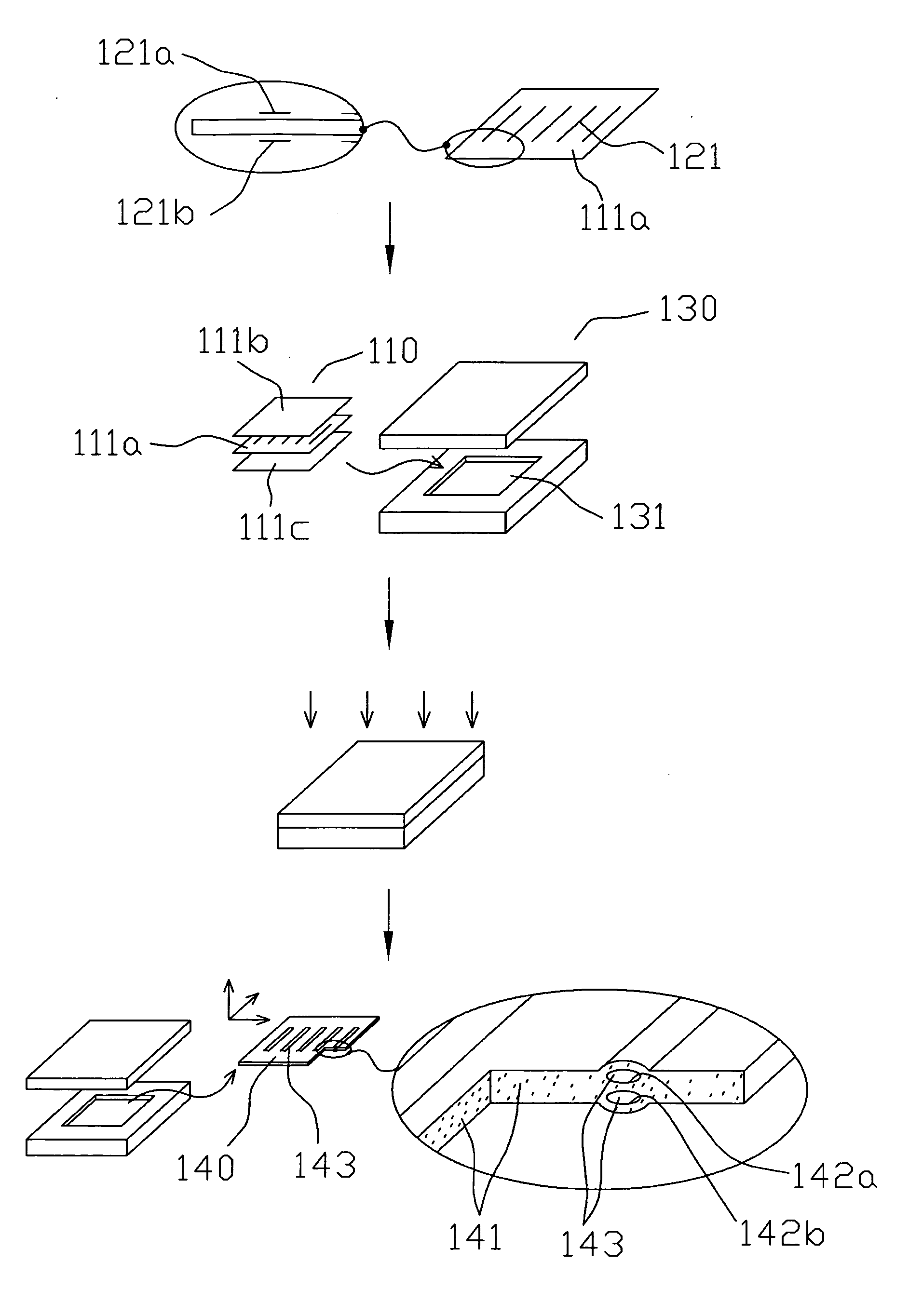
[0095]FIG. 1 illustrates a manufacturing process of a cross-linked foam having more than one internally-formed surface according to a first embodiment of the present invention.

[0096] Material Preparation: Three sheets of film type materials 111a, 111b and 111c having a foaming rate of 150%, which are calender-molded, are cut to have the size of thickness 2 mm, width 100 mm, and length 100 mm.

[0097] Interfacing Pattern Formation: A silkscreen printing is performed on both sides of the first film type material 111a among the three sheets of film type materials 111a, 111b and 111c. Interfacing patterns 121a and 121b are printed on the first film type material 111a in a thickness of 70 micrometers by using a urethane-resin-based ink and the resultant structure is dried at a temperature of 60 degrees Celsius for 15 minutes. The interfacing patterns 121a and 121b have five-striped pattern shapes each having a width 2 mm and a length 50 mm, and each of the five-striped pattern shapes are...

second embodiment

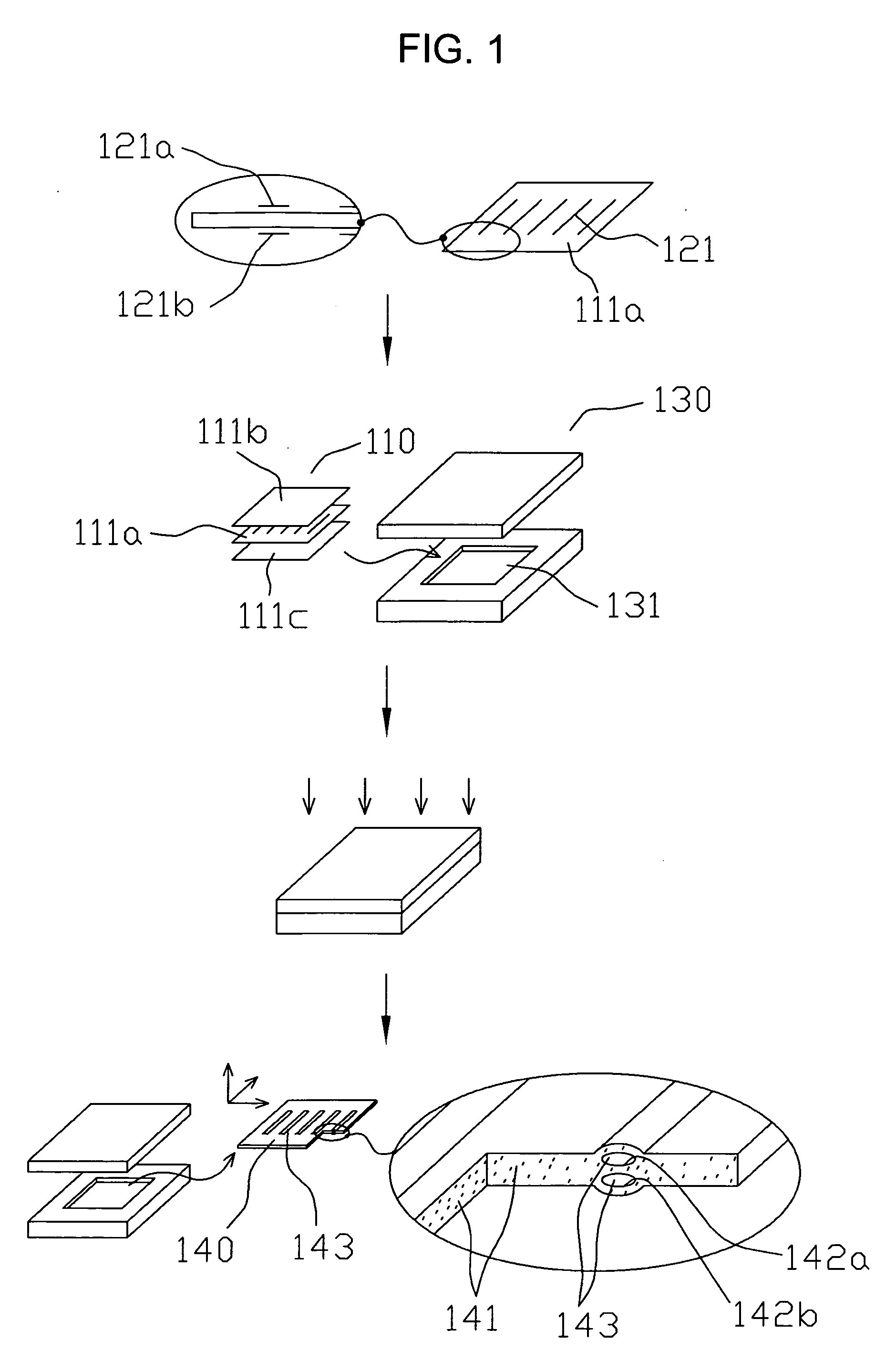
[0100]FIG. 2 illustrates a manufacturing process of a cross-linked foam according to a second embodiment of the present invention. The second embodiment is a modification of the first embodiment in which a double-layered internally-formed surfaces are formed in the foam.

[0101] Material Preparation: Three sheets of white materials 211a, 211b, and 211c having a foaming rate of 150% are injection-molded.

[0102] Interfacing Pattern Formation: Each surface of the first and second white materials 211a and 211b is pad printed to form first and second interfacing patterns 221 and 222. The first interfacing pattern 221 is formed on the first white material 211a, and has nine doughnut type patterns each of which has an inner circle having a diameter of 2 mm arranged at the center of the doughnut type pattern and an outer circle having a diameter of 6 mm. The second interfacing pattern 222 is formed on the second white material 211b, and is designed with sixteen circle patterns each having a ...

third embodiment

[0105]FIG. 3 illustrates a manufacturing process of a foam according to a third embodiment of the present invention. The third embodiment is a modification of the second embodiment.

[0106] Material Preparation: Two sheets of materials 311a and 311b having a foaming rate of 150% are extrusion-molded or calender-molded. Each of the materials has a width of 40 inches, a length of 10 yards, and a thickness of 2 mm.

[0107] Interfacing Pattern Formation: Peanut-shaped patterns 321 constituted by a pair of adjacent circles each of which has a diameter 6 mm, are arranged on the first material 311a. Each of the adjacent circles of the peanut-shaped patterns 321 has a centric circular opening having a diameter of 2 mm. Each of the peanut-shaped patterns are printed using a epoxy-resin-based ink on the first material 311a at a thickness of 40 micrometers with a margin of 10 mm from the up-and-bottom and left-and-right neighboring peanut-shaped patterns, and thermal-dried at a temperature of 60...


PUM

PropertyMeasurementUnit
Pressureaaaaaaaaaa
Structureaaaaaaaaaa
Surface roughnessaaaaaaaaaa

Abstract

A method and device for forming a cross-linked foam and a cross-linked foam are provided. The method includes the steps of preparing at least one foaming material for cross-linked foaming, the foaming material processed to have a plane or three-dimensional shape; forming at least one interfacing pattern on a surface of at least one of the foaming material using at least one interfacing material that prevents chemical and physical interaction between the foaming materials; and forming a cross-linked foam by foaming the foaming material having the interfacing pattern thereon, the cross-linked foam having a foam body and an internally-formed surface.

Description

BACKGROUND OF THE INVENTION [0001] 1. Field of the Invention [0002] The present invention relates to a cross-linked foam and a manufacturing method thereof. More specifically, it relates to a cross-linked foam having various inner cavity structures formed by an internally-formed surface and a method and device for forming the inner cavity structure simultaneously with a body of the cross-linked foam. [0003] 2. Discussion of the Related Art [0004]FIG. 30 is a flow chart illustrating process steps for manufacturing cross-linked foams according to a related art. In step S10, source materials including main material such as diverse resins and other additives are first weighed in accordance with a designed mixture standard depending on what kind of cross-linked foam is fabricated. Then the weighed resins and additives are mixed with a cross-liking agent and a foaming agent in a hermetical mixer or kneader in a milling process. Therefore, a mixed chemical compound is prepared. [0005] In s...

Claims


Application Information

Patent Timeline
IPC IPC(8): B32B3/26B29C67/20B32B17/10A43B7/08A43B13/04C08J9/22A43B13/18A43B13/20A43B17/08A43B23/02B29C44/06B29C44/56B29D35/12B29D35/14
CPCA43B7/08Y10T428/31518A43B13/186A43B13/188A43B13/20A43B17/08B29C44/06B29C44/569B29D35/122B29D35/126B29D35/128B29D35/142B29D35/146B29D35/148A43B7/085Y10T428/249953A43B13/04C08J9/22
Inventor PARK, JANG-WON
Owner PARK LTD
Why Eureka
Try Eureka