Gas recuperative flameless thermal oxidizer

a flameless thermal oxidizer and flameless technology, applied in the direction of capillary burners, combustion types, furnaces, etc., can solve the problems of uncontrollable production of undesirable side products, unsatisfactory use of free flames to oxidize such effluents, etc., and achieve the effect of increasing or decreasing the size of the matrix bed

Inactive Publication Date: 2006-04-20
SELAS FLUID PROCESSING CORP
View PDF36 Cites 19 Cited by
  • Summary
  • Abstract
  • Description
  • Claims
  • Application Information

AI Technical Summary

Benefits of technology

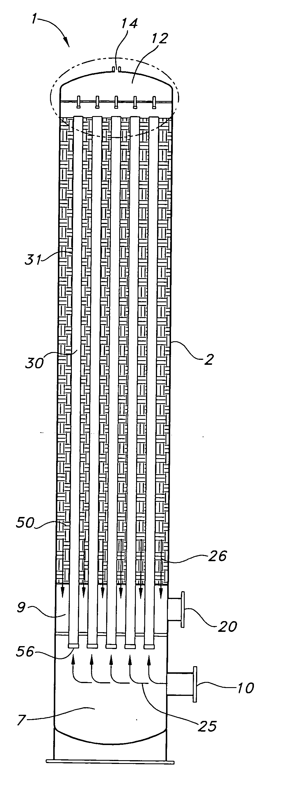
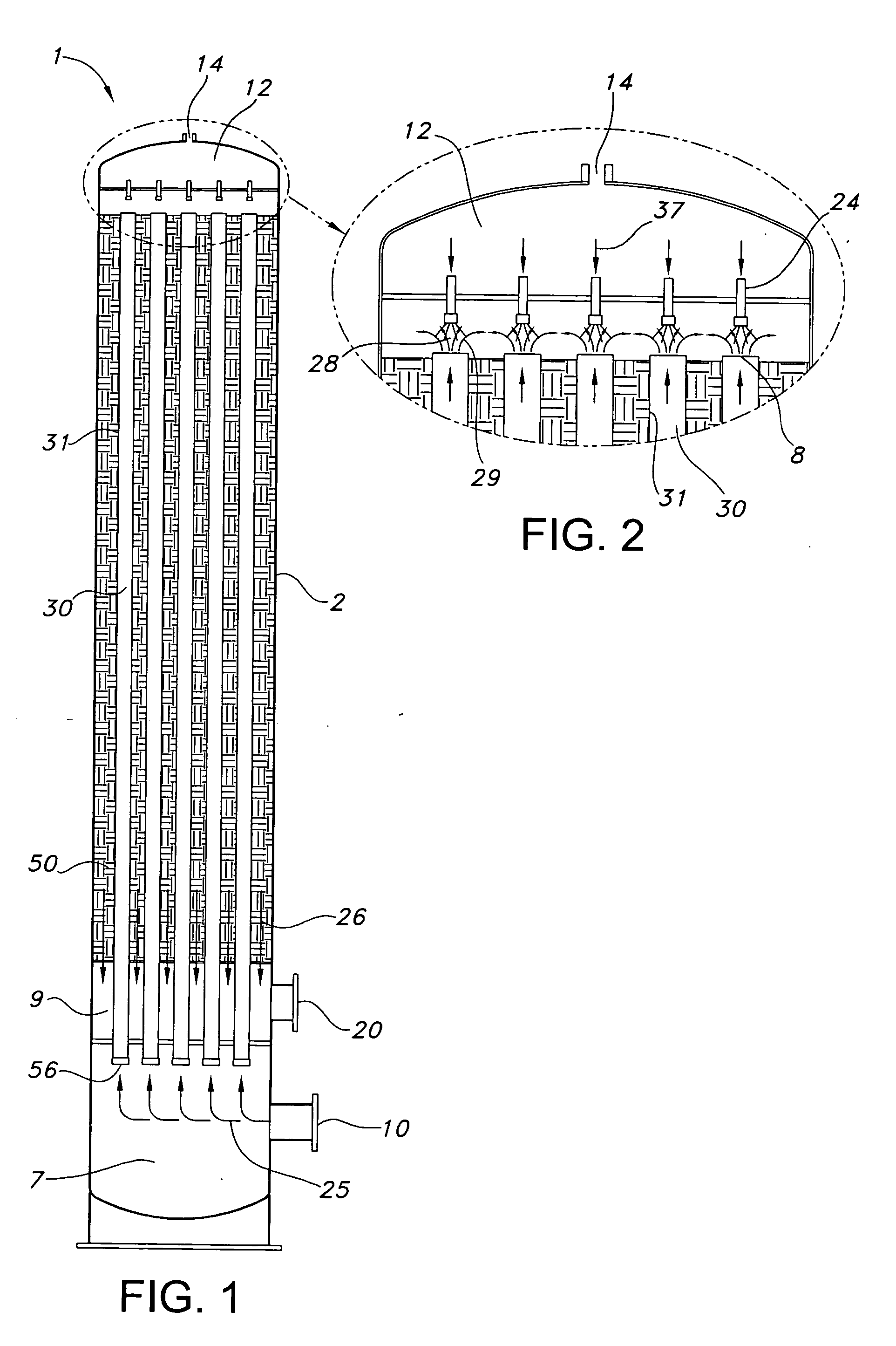
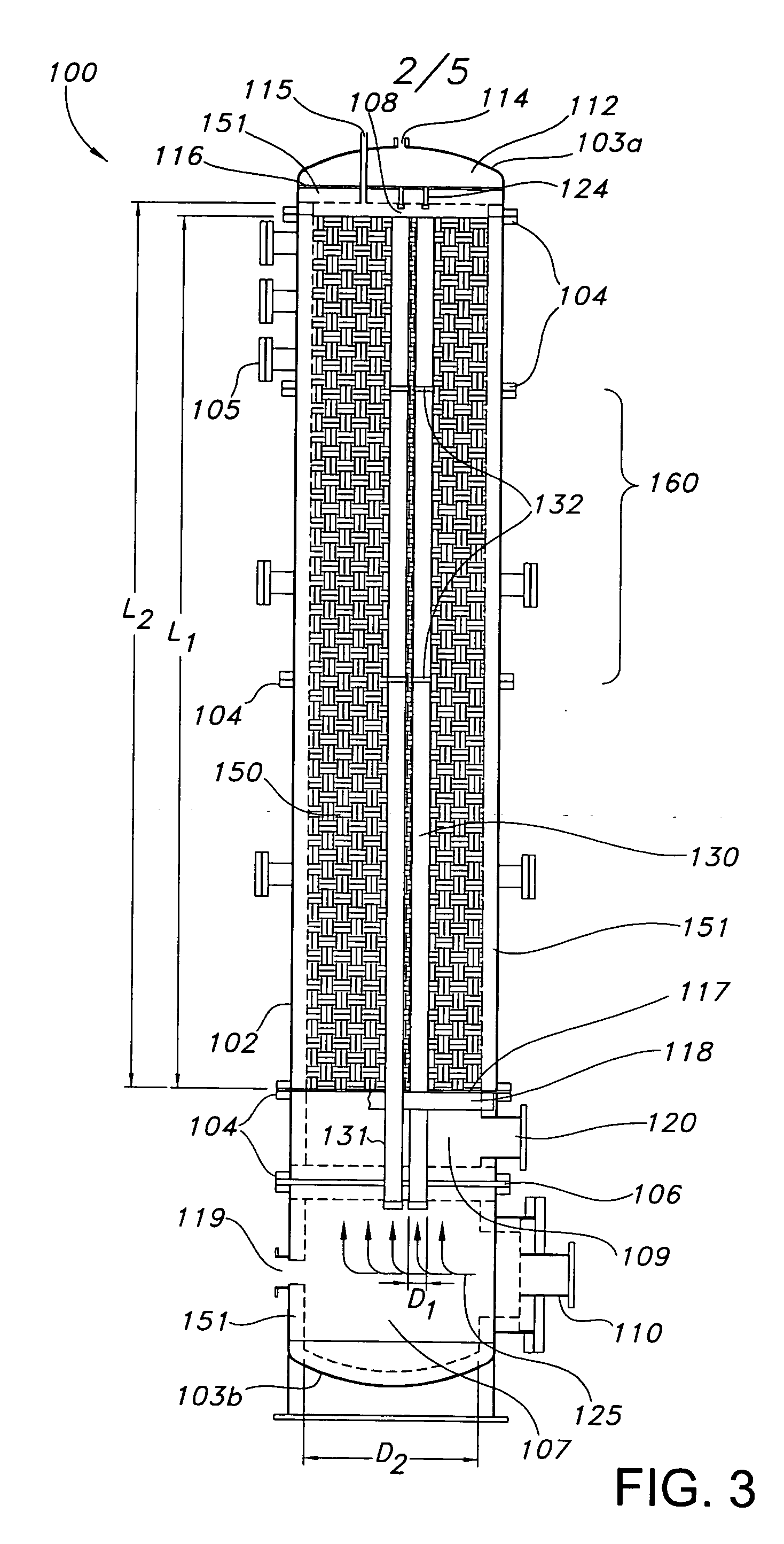
[0014] In another aspect, the invention provides a gas recuperative flameless thermal oxidizer having an enclosure extending between opposed end portions, a matrix bed contained within the enclosure, feed tubes extending into the enclosure and at least partially within the matrix bed, and means for adjusting the distance between the opposed end portions of the enclosure to increase or decrease the size of the matrix bed.

Problems solved by technology

However, with increasing demands on the environmental control of emissions, the use of free flames to oxidize such effluents is in many cases unsatisfactory, since a free flame frequently results in incomplete combustion and uncontrollable production of undesirable side products, including for example carbon monoxide and nitrogen oxides.

Method used


Image

  • Gas recuperative flameless thermal oxidizer
  • Gas recuperative flameless thermal oxidizer
  • Gas recuperative flameless thermal oxidizer

Examples


example

[0086] In FIG. 9, there is shown the results of a computer simulation of the temperature profile in a flameless thermal oxidizer according to one embodiment of the invention, with the results shown as a schematic illustration of calculated isotherms. FIG. 9 illustrates this temperature profile as it relates to an embodiment of a feed tube 231 and a mixing region 228 similar to region 28. The calculated isotherms predict the heat transfer flux between the feed tube wall and the matrix bed.

[0087] The map shows lines indicating temperatures T1 to T10 in relation to one side of the feed tube 231, with temperatures outside the tube indicated above the wall of the tube indicated at 231 and temperatures inside the tube 231 indicated below the wall. Mixing region 228 is indicated in the area proximal to the end of feed tube 231.

[0088] The simulation illustrated in FIG. 9 is based upon the parameters is defined in the following table:

ParameterValueFeed SpeciesMethane-Air Mixture: 0.011 w...


PUM


Abstract

The invention provides a gas recuperative flameless thermal oxidizer. The oxidizer includes a matrix bed and at least one feed passage extending at least partially within the matrix bed. The feed passage has an inlet configured to receive combustible vapor or an air-combustible vapor mixture and an outlet configured to deliver the combustible vapor or the air-combustible vapor mixture into the matrix bed. The feed passage has a cross-sectional area and a length within the matrix bed, wherein a ratio of the length (ft) to the cross-sectional area (in2) is at least about 0.5:1.

Description

FIELD OF THE INVENTION [0001] This invention relates to a flameless thermal oxidizer. More particularly, this invention relates to a gas recuperative flameless thermal oxidizer and a method for oxidizing combustible vapor in a flameless thermal oxidizer. BACKGROUND OF THE INVENTION [0002] Many process streams of vapors, such as effluents from chemical processing plants, refineries, etc., utilize oxidizers to destroy the combustible vapor prior to release to the atmosphere. However, with increasing demands on the environmental control of emissions, the use of free flames to oxidize such effluents is in many cases unsatisfactory, since a free flame frequently results in incomplete combustion and uncontrollable production of undesirable side products, including for example carbon monoxide and nitrogen oxides. Thus, methods for destroying combustible streams to a high level of conversion with a minimum of pollutant production and in an energy-efficient manner are in continuing and incre...

Claims


Application Information

Patent Timeline
Patent Type & Authority Applications(United States)
IPC IPC(8): F23D3/40
CPCF23C99/006F23G7/066F23G2202/50Y02E20/34
Inventor HUEBNER, WILLIAMMAINE, GREGORYFALCONE, PETER
Owner SELAS FLUID PROCESSING CORP
Why Eureka
Try Eureka