

Apparatus and method for correction of abberations in laser system optics
a laser system optics and abberation technology, applied in laser surgery, medical science, surgery, etc., can solve problems such as vision impairment, defective eye condition, and varying degrees of vision impairmen
- Summary
- Abstract
- Description
- Claims
- Application Information
AI Technical Summary
Benefits of technology
Problems solved by technology
Method used
Image

Examples
Embodiment Construction
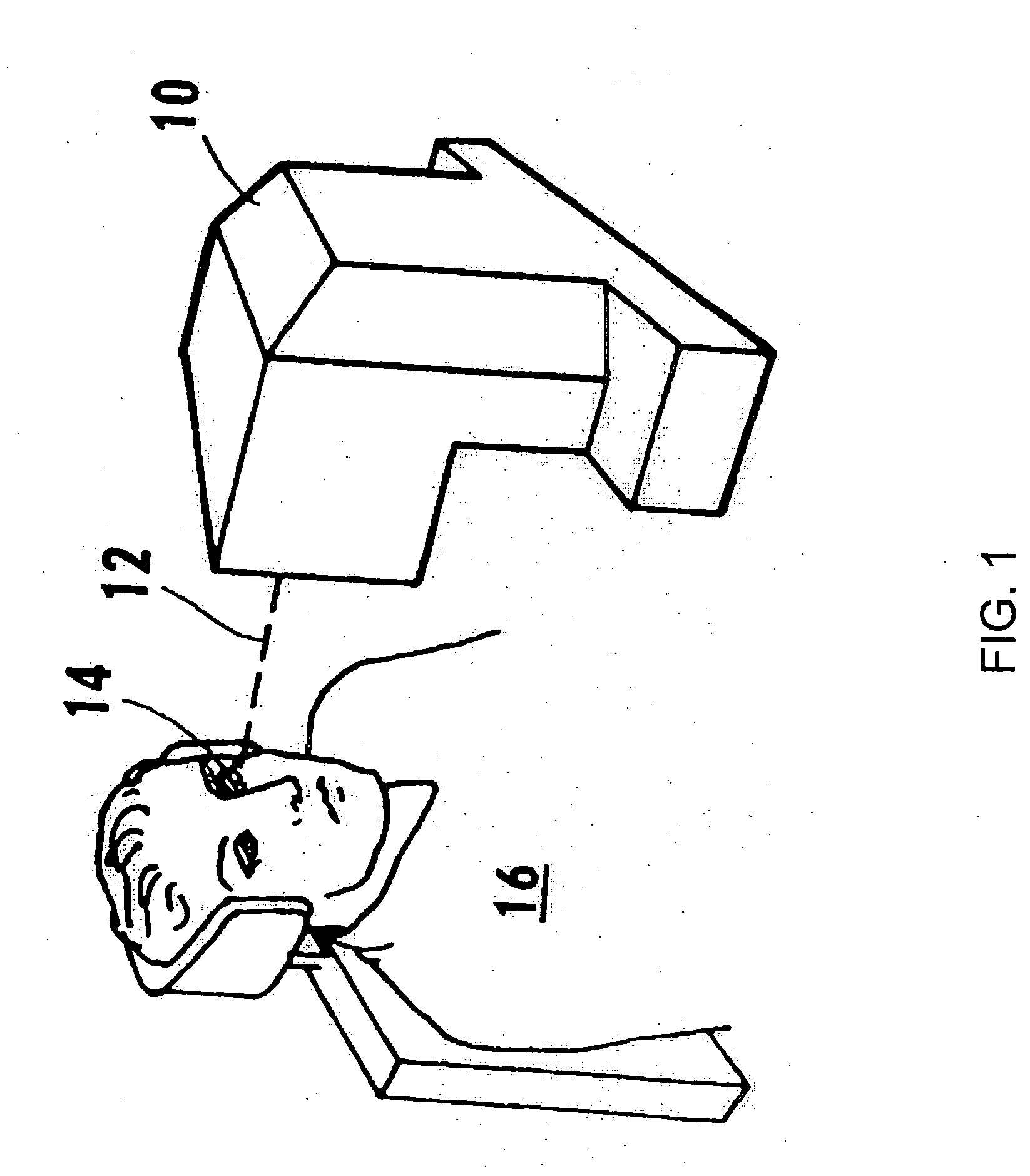
[0026] Referring initially to FIG. 1, depicting a prior art image, an apparatus 10 for generating a laser beam 12 is shown. The laser beam 12 is directed onto an eye 14 of a patient 16. For purposes of the present invention, the apparatus 10 is capable of generating a pulsed laser beam 12 having physical characteristics similar to those of the laser beams generated by a laser system as disclosed and claimed in U.S. Pat. No. 4,764,930, which is exclusively licensed to the assignee of the present invention. Various laser sources may be used with the inventive system and method, including infrared, visible, and UV lasers. Further, laser sources to be used with the inventive system may be continuous wave, Q-switched pulse, and mode-locked ultrashort pulse lasers. Although the following is not an exhaustive list, lasers of the foregoing type may be used with the present invention.
[0027] In one embodiment, the present invention contemplates the use of a pulsed laser beam 12 which has pul...
PUM
 Abstract
Description
Claims
Application Information