Tank for heat exchanger

a technology of heat exchanger and tank, which is applied in the direction of indirect heat exchangers, lighting and heating apparatus, stationary conduit assemblies, etc., can solve the problems of inability to detect the tank occurring at this face, the strength of the tank is greatly compromised, and the bypass leakage of heat exchange medium. achieve the effect of high strength

Inactive Publication Date: 2006-04-27
ZEXEL VALEO CLIMATE CONTROL CORP SAITAMA
View PDF7 Cites 8 Cited by
  • Summary
  • Abstract
  • Description
  • Claims
  • Application Information

AI Technical Summary

Benefits of technology

[0016] In this structure, even if a plurality of slits are formed in the quantity corresponding to the number of chambers with each slit running over all the side faces of the co

Problems solved by technology

The heat exchanger disclosed in Japanese Unexamined Patent Publication No. 2001-74388 poses a problem in that since a single slit extending substantially over the full width of the tank along the air flow direction needs to be formed, the strength of the tank is greatly compromised.
In addition, sin

Method used


Image

  • Tank for heat exchanger
  • Tank for heat exchanger
  • Tank for heat exchanger

Examples


Embodiment Construction

[0028] The following is an explanation of preferred embodiments of the present invention, given in reference to the attached drawings.

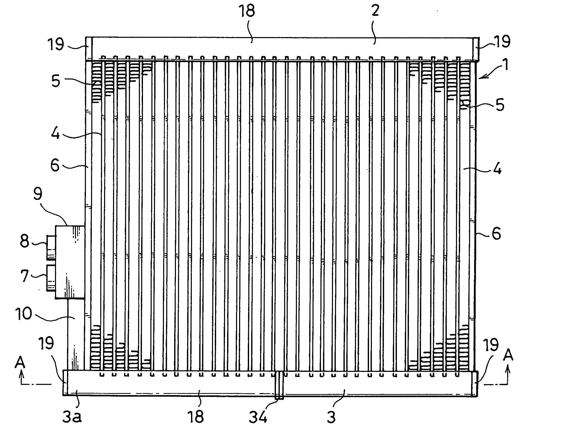
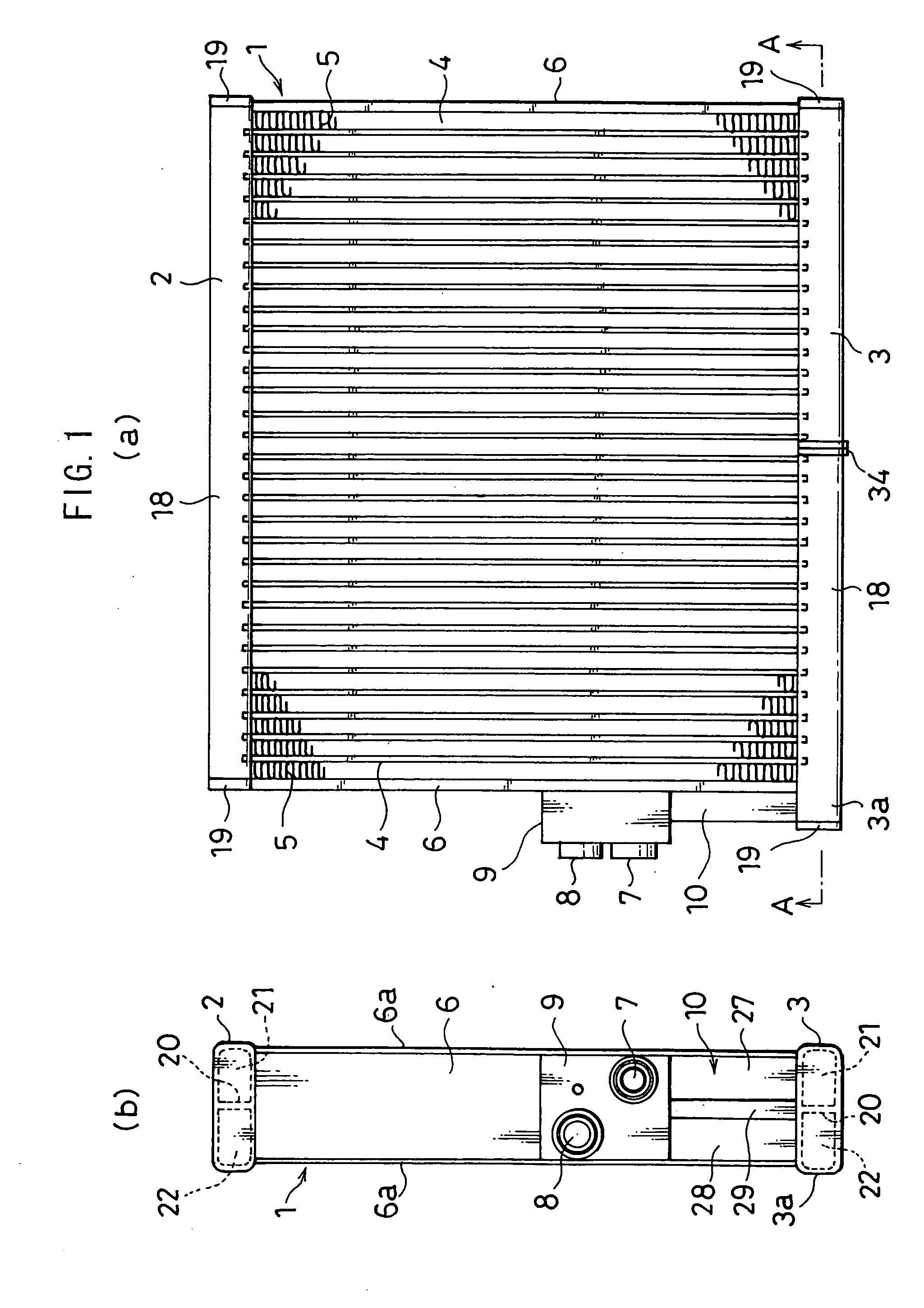
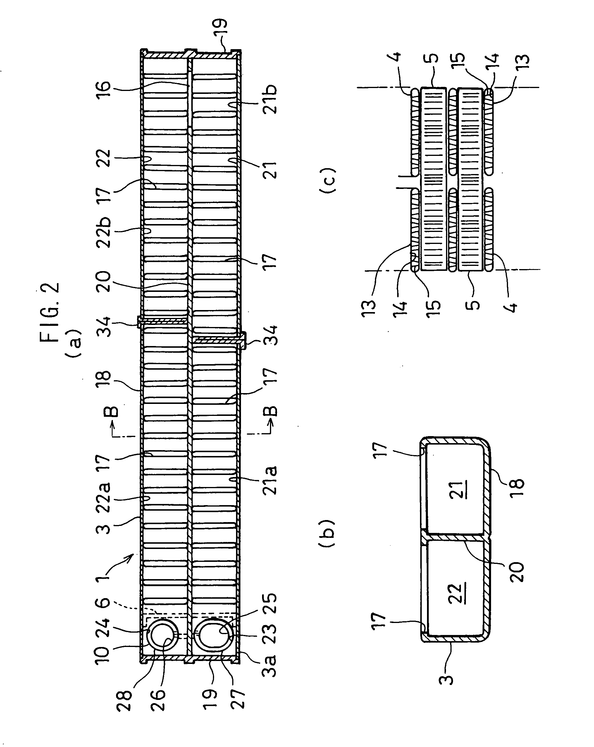
[0029] A heat exchanger 1 shown in FIGS. 1 and 2 may be used, for instance, as an evaporator constituting part of a freezing cycle of an on-vehicle air-conditioning system. The heat exchanger 1 comprises a pair of tanks 2 and 3, a plurality of heat exchanging tubes 4 communicating between the tanks 2 and 3, corrugated outer fins 5 inserted and bonded between the individual heat exchanging tubes 4, side plates 6 disposed at the two ends of the layered heat exchanging tube assembly and a side tank 10 at which a connector 9 having heat exchange medium intake / outlet portions 7 and 8 is mounted. The connector 9 is connected with an expansion valve (not shown). At the heat exchanger 1, a heat exchange medium supplied through the expansion valve (not shown) flows in via the side tank 10, the heat exchange medium then exchanges heat with the air passing betw...


PUM


Abstract

In tubular portion of a tank, slits are formed in each side face of chambers or across all side faces of the chambers. For partition plates that are to be inserted from the slits, groove portions in which the partition plates are fitted are formed by cutting portions to which the partition plates butt. The slits are formed in the chambers at positions relatively shifted from each other in a direction in which tubes are layered. This structure guarantees that, in the tank for a heat exchanger, bypass leakage of a heat exchange medium between sub-chambers is prevented from occurring when the partition plates are inserted in the tank from the slits provided on the tank side faces. Further, the tank can maintain required strength even if the slits are formed in it.

Description

[0001] This application is a U.S. National Phase Application under 35 USC 371 of International Application PCT / JP2003 / 014340 filed on Nov. 12, 2003.TECHNICAL FIELD [0002] The present invention relates to a tank used in, for instance, an evaporator of a freezing cycle in an on-vehicle air-conditioning system, and more specifically, it relates to the structure of a tank formed as a component separate from the heat exchanging tubes. BACKGROUND ART [0003] There are heat exchangers known in the related art achieved with a heat exchange medium flowing through at least four passes and having a tank provided as a component separate from tubes, in which any defective bonding of a partitioning portion can be detected with ease (see, for instance, Japanese Unexamined Patent Publication No. H10-19490). [0004] In addition, there is a structure known in the related art adopted in a heat exchanger achieved with a heat exchange medium flowing through at least four passes and having a tank provided ...

Claims


Application Information

Patent Timeline
IPC IPC(8): F28D1/02F28D1/053F28F9/02
CPCF28D1/05391F28F9/0204
Inventor OHATA, HAJIMEMUNEO, SAKURADAYOSHIHISA, ETONAOTO, TAKAYANAGI
Owner ZEXEL VALEO CLIMATE CONTROL CORP SAITAMA
Why Eureka
Try Eureka