Latch assembly

a technology of latches and bolts, which is applied in the direction of fastening means, mechanical devices, and applications of locks, etc., can solve the problems of reducing the distance between the latch and the striker and/or the shoot bolt, affecting the effect of the latch position, and affecting the safety of the latch

Inactive Publication Date: 2006-04-27
MERITOR TECH
View PDF16 Cites 18 Cited by
  • Summary
  • Abstract
  • Description
  • Claims
  • Application Information

AI Technical Summary

Benefits of technology

[0008] Accordingly, one aspect of the present invention provides a latch assembly including a mouth for receiving a striker and a releasable latch bolt mechanism for automatically retaining the striker within the mouth. The mouth includes a deformable unitary jaw member defining opposing first and second jaw walls and an intermediate base portion. The first and second ja...

Problems solved by technology

Thus, with the rear doors open, a certain amount of deflection of the roof and the side panels of the rear load space may occur, and a certain amount of flexing of the doors may also occur.
The combination of these factors may lead to difficulties in locating the latch with the striker and/or the shoot bolts in the respective holes due to movement of the rear doors out of their proper alignment.
This may in turn lead to difficulties in satisfactorily latching the doors.
Additionally, the deflection of the roof, t...

Method used


Image

  • Latch assembly
  • Latch assembly
  • Latch assembly

Examples


Embodiment Construction

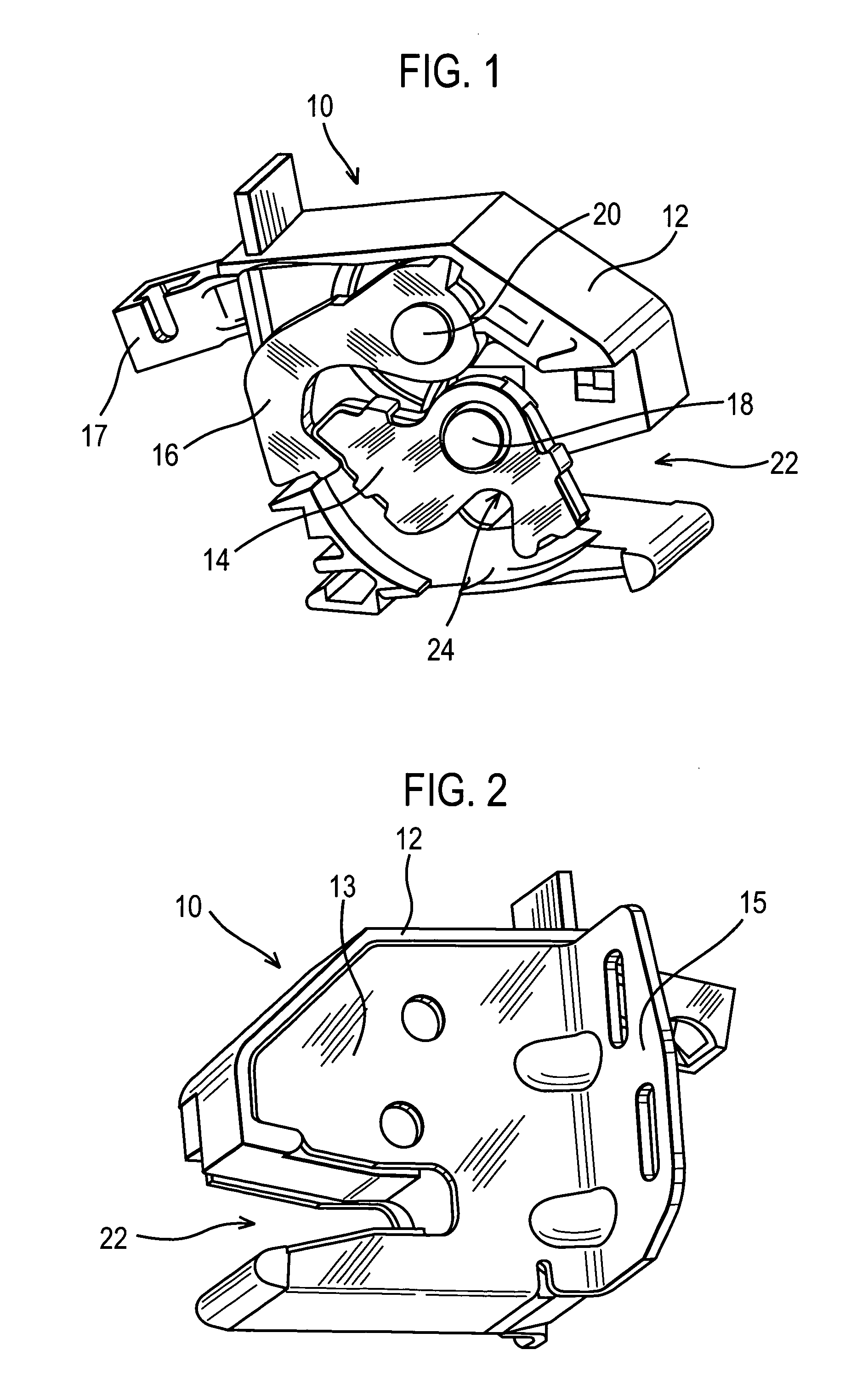
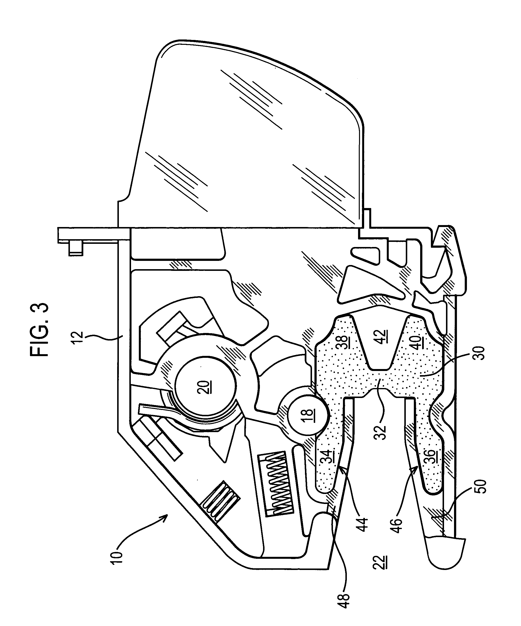
[0019]FIGS. 1 and 2 illustrate a latch assembly 10 including a latch chassis 12 on which a latch bolt in the form of a rotatable claw 14 and a pawl 16 are pivotally mounted. The pawl 16 is typically in driven engagement with a latch operator, such as an inside release handle of a vehicle door to which the latch assembly 10 is mounted, either directly or more usually indirectly, via a primary latch (not shown) itself controlled by an inside handle and / or an outside handle. The primary latch has an output to the pawl 16 via a bowden cable or the like (not shown) and a release lever 17.

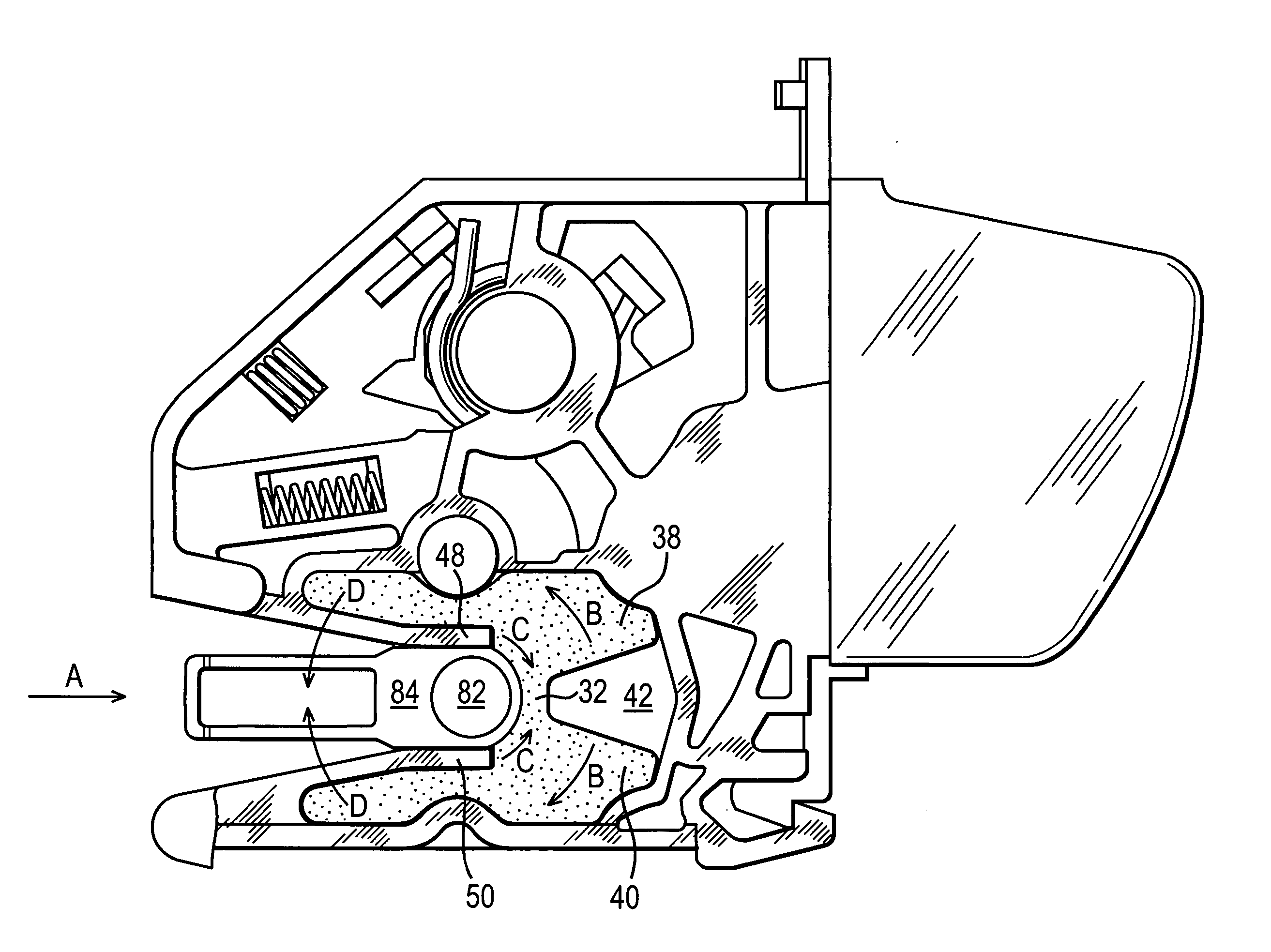
[0020]FIG. 1 shows the latch assembly 10 in a closed latched position with the claw 14 configured to retain a striker bar 82 of a striker assembly 70 within a claw recess 24 (see FIG. 7). The claw 14 is retained in a closed position by the pawl 16. The pawl 16 may be lifted by the release lever 17 to release the claw 14.

[0021] The sides of the latch chassis 12 are enclosed by side plates 13 which def...


PUM


Abstract

A latch assembly includes a mouth for receiving a striker and a releasable latch bolt mechanism for automatically retaining the striker within the mouth. The mouth includes a deformable unitary jaw member defining opposing first and second jaw walls and an intermediate base portion. The jaw walls and the base portion are arranged to engage the striker. The base portion is configured to deflect inwardly upon receiving the striker. The inward deflection of the base portion causes a partial closure of the unitary jaw member by way of associated deflection of at least one of the jaw walls to reduce the distance between the jaw walls.

Description

REFERENCE TO RELATED APPLICATION [0001] This application claims priority to United Kingdom Patent Application GB 0423702.0 filed on Oct. 26, 2004. BACKGROUND OF THE INVENTION [0002] The present invention relates generally to a latch assembly for a vehicle and to a striker. More particularly, the present invention relates to a latch assembly including a latch and a striker having cooperating engagement means. [0003] Light commercial vehicles, such as panel vans (i.e., vans in which a load space is enclosed), typically include a relatively large rear opening that is closeable by two rear doors hinged to a rear most edge of each side of the van. A latch is typically provided partially up a shut-face of one of the rear doors. The latch is arranged to latch with a complementary striker provided on the shut-face of the other of the rear doors when the doors are closed. Typically, the latch may also operate shoot bolts or supplementary latches which are fitted to upper and lower edges of t...

Claims


Application Information

Patent Timeline
IPC IPC(8): E05C19/10E05B17/00E05B65/12E05B65/32
CPCE05B85/02E05B85/26E05B77/38Y10T292/0921
Inventor ROUSSEL, JEROME P.
Owner MERITOR TECH
Why Eureka
Try Eureka