Apparatus and method for testing a signal path from an injection point

a signal path and injection point technology, applied in special-purpose recording/indication apparatus, instruments, wireless communication, etc., can solve the problems of cumbersome and expensive implementation, limited frequency range of directional couplers, and bulky and expensive directional couplers, and achieve accurate determination of electronic signal path characteristics.

Active Publication Date: 2006-04-27
UNIV OF UTAH RES FOUND
View PDF19 Cites 36 Cited by
  • Summary
  • Abstract
  • Description
  • Claims
  • Application Information

AI Technical Summary

Benefits of technology

[0011] It has been recognized that it would be advantageous to develop a flexible, portable testing device that can be connected to

Problems solved by technology

These conventional techniques suffer from a number of disadvantages that make them cumbersome and expensive to implement.
These directional couplers are bulky and expensive.
Directional couplers are also limited in frequency range, which limits the type of test signals that can be injected.
Although SWR can be used without directional couplers, SWR is typically limited to providing a pass/fail characterization of the signal path.
SWR does not perform well when there are multiple problems in the signal path.
Isolation of the actual location of the problem along the signal path is difficult

Method used


Image

  • Apparatus and method for testing a signal path from an injection point
  • Apparatus and method for testing a signal path from an injection point
  • Apparatus and method for testing a signal path from an injection point

Examples


Embodiment Construction

[0031] Reference will now be made to the exemplary embodiments illustrated in the drawings, and specific language will be used herein to describe the same. It will nevertheless be understood that no limitation of the scope of the invention is thereby intended. Alterations and further modifications of the inventive features illustrated herein, and additional applications of the principles of the inventions as illustrated herein, which would occur to one skilled in the relevant art and having possession of this disclosure, are to be considered within the scope of the invention.

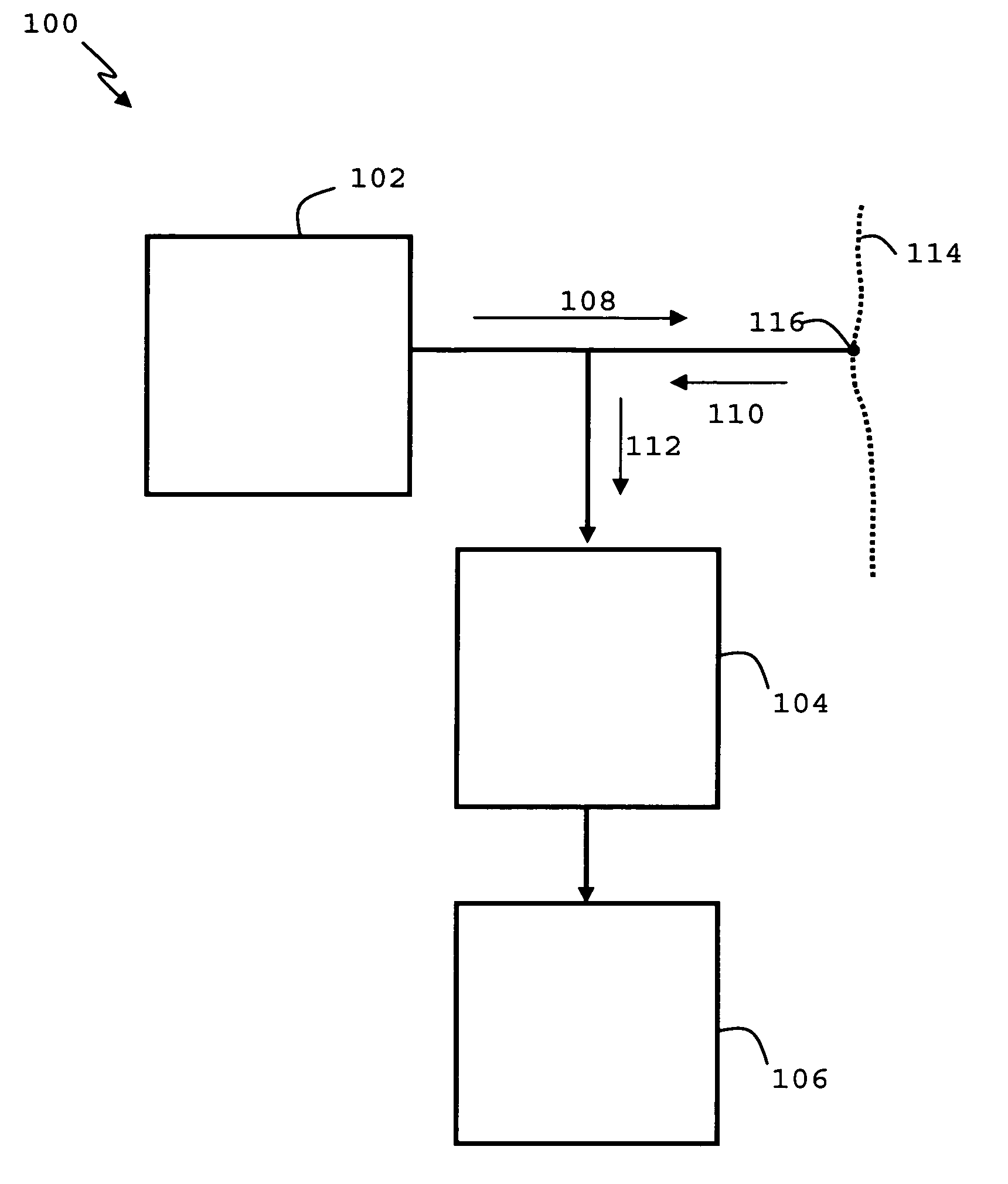
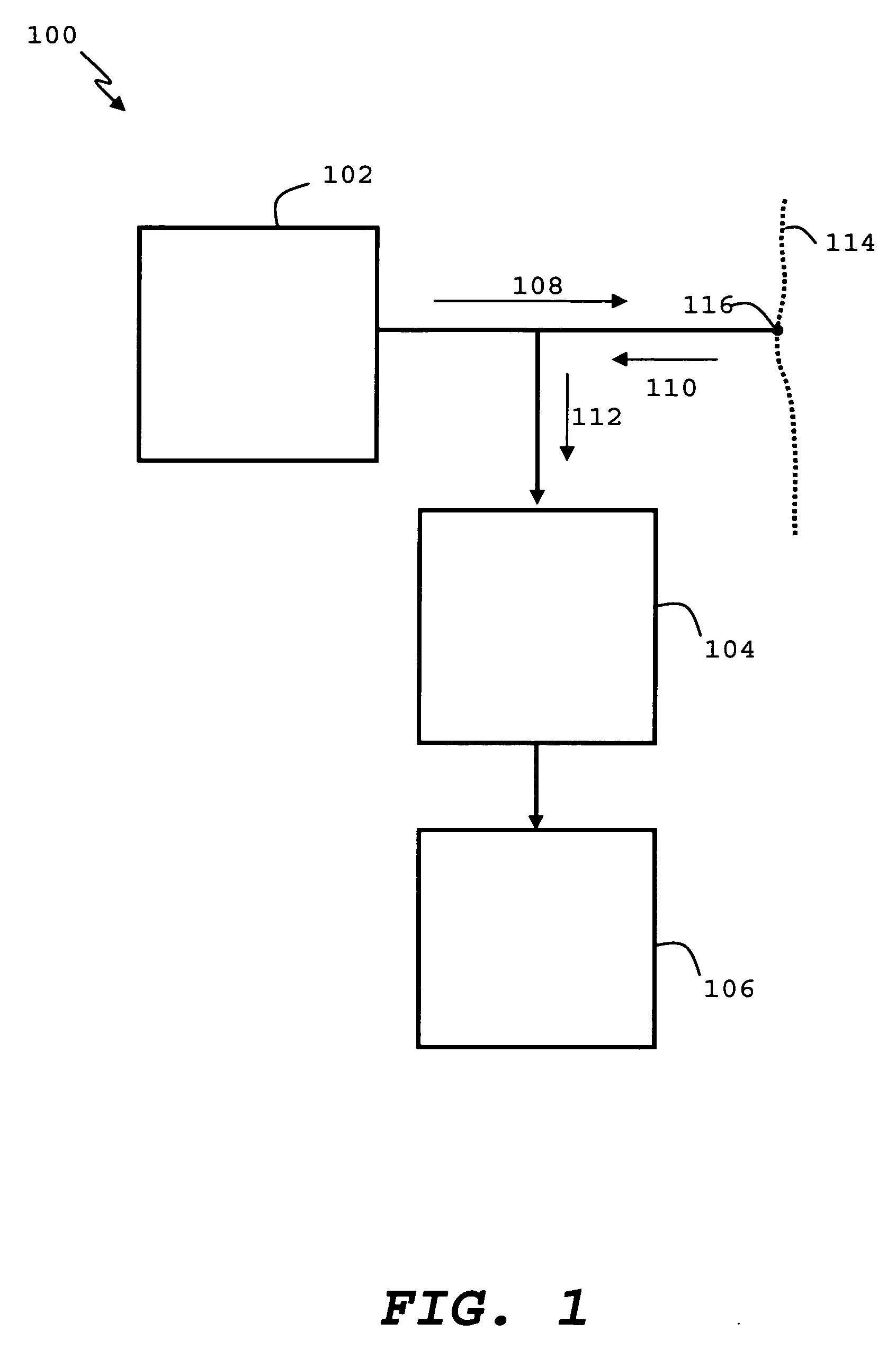
[0032]FIG. 1 illustrates a block diagram of an apparatus for testing the integrity of a signal path, in accordance with an embodiment of the present invention. The apparatus, referred to as a Mixed Signal Reflectometer (MSR), is shown generally at 100. The MSR 100 may include a signal generator 102 configured to inject a test signal 108 into the signal path 114 at an injection point 116 when coupled to the sign...


PUM


Abstract

The invention includes an apparatus and method for testing an electronic signal path. The apparatus includes a signal generator (102) configured to inject a test signal into the electronic signal path at an injection point when coupled to the signal path. The apparatus further includes a detector (104) coupled to the signal generator and configured to receive a combined signal at the injection point when coupled to the electronic signal path and determine an autocorrelation of the combined signal. The apparatus further includes an analyzer coupled to the detector and configured to determine a characteristic of the electronic signal path from the autocorrelation. The method includes injecting (902) a test signal into the electronic signal path an injection point, receiving (904) a combined signal from the electronic signal path at the injection point, determining (906) an autocorrelation of the combined signal, and estimating (908) a characteristic of the electronic signal path from the autocorrelation.

Description

[0001] This application is a continuation-in-part of copending PCT Application No. PCT / US2004 / 010127 entitled “Apparatus and Method for Testing a Signal Path From an Injection Point” filed on Mar. 31, 2004 which claims the benefit of U.S. Application No. 60 / 459,4828 filed on Mar. 31, 2003 entitled “Mixed Signal Reflectometer Apparatus and Method for Determining the Integrity of Signal Paths.”[0002] This application is also continuation-in-part of copending U.S. application Ser. No. 11 / 133,145 filed on May 18, 2005 entitled “Device and Method for Detecting Anomolies in a Wire and Related Sensing Methods” which is a continuation-in-part of PCT Application No. PCT / US03 / 37233 filed on 19 Nov. 2003 entitled “Device and Method for Detecting Anomolies in a Wire and Related Sending Methods” which claims the benefit of U.S. Application No. 60 / 427,737 filed on 19 Nov. 2002 entitled “Handheld Device for Detecting Open, Short and Location of Anomaly on a Wire,” U.S. Application No. 60 / 455,788 f...

Claims


Application Information

Patent Timeline
IPC IPC(8): G01R31/08H04W24/00
CPCH04W24/00
Inventor FURSE, CYNTHIALO, CHETCHUNG, YOU CHUNG
Owner UNIV OF UTAH RES FOUND
Why Eureka
Try Eureka