Flat display device

Inactive Publication Date: 2006-04-27
TOSHIBA MATSUSHITA DISPLAY TECH
View PDF5 Cites 19 Cited by
  • Summary
  • Abstract
  • Description
  • Claims
  • Application Information

AI Technical Summary

Benefits of technology

[0010] The present invention has been made in consideration of these circumstances, and its object is to provide a flat display device with improved display quality in which light leakage is prevented.
[0011] According to an aspect of the invention, there is provided a flat display device comprising: a flat display panel provided with a first main surface having a display region in which an image is displayed and a second main surface opposed to the first main surface; a frame which is located on the second main surface side of the flat display panel and holds the flat display panel; and a frame-shaped bezel fixed to the frame. The bezel includes a surface portion which has an end side on the boundary with the display region of the flat display panel and covers the first main surface of the flat display panel with the display region exposed, a side face portion which covers at least a part of a side face of the frame, a reverse portion which extends covering at least a part of a reverse surface of the frame, a fixed portion provided on the reverse portion of the bezel and fixed to the frame, and a stress easing portion which is situated near a shortest path extending from the fixed portion of the bezel toward the end side and eases stress in a direction such that the surface portion and the flat display panel are separated from each other.

Problems solved by technology

With the flat display device constructed in this manner, however, the position and angle of bend of the bendable portion cannot be easily kept constant with high accuracy.
In this case, light may possibly leak through this gap, thereby lowering the display quality of the display device.

Method used


Image

  • Flat display device
  • Flat display device
  • Flat display device

Examples


first embodiment

[0026] A liquid crystal display device according to this invention will now be described in detail with reference to the drawings.

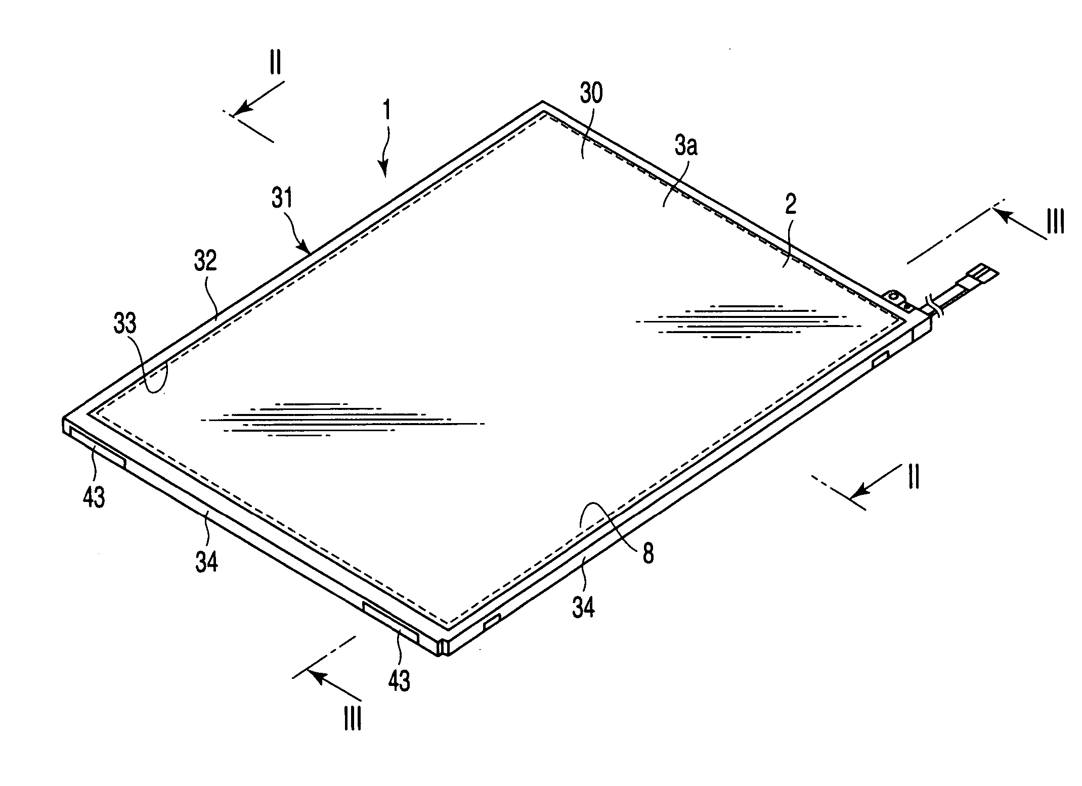
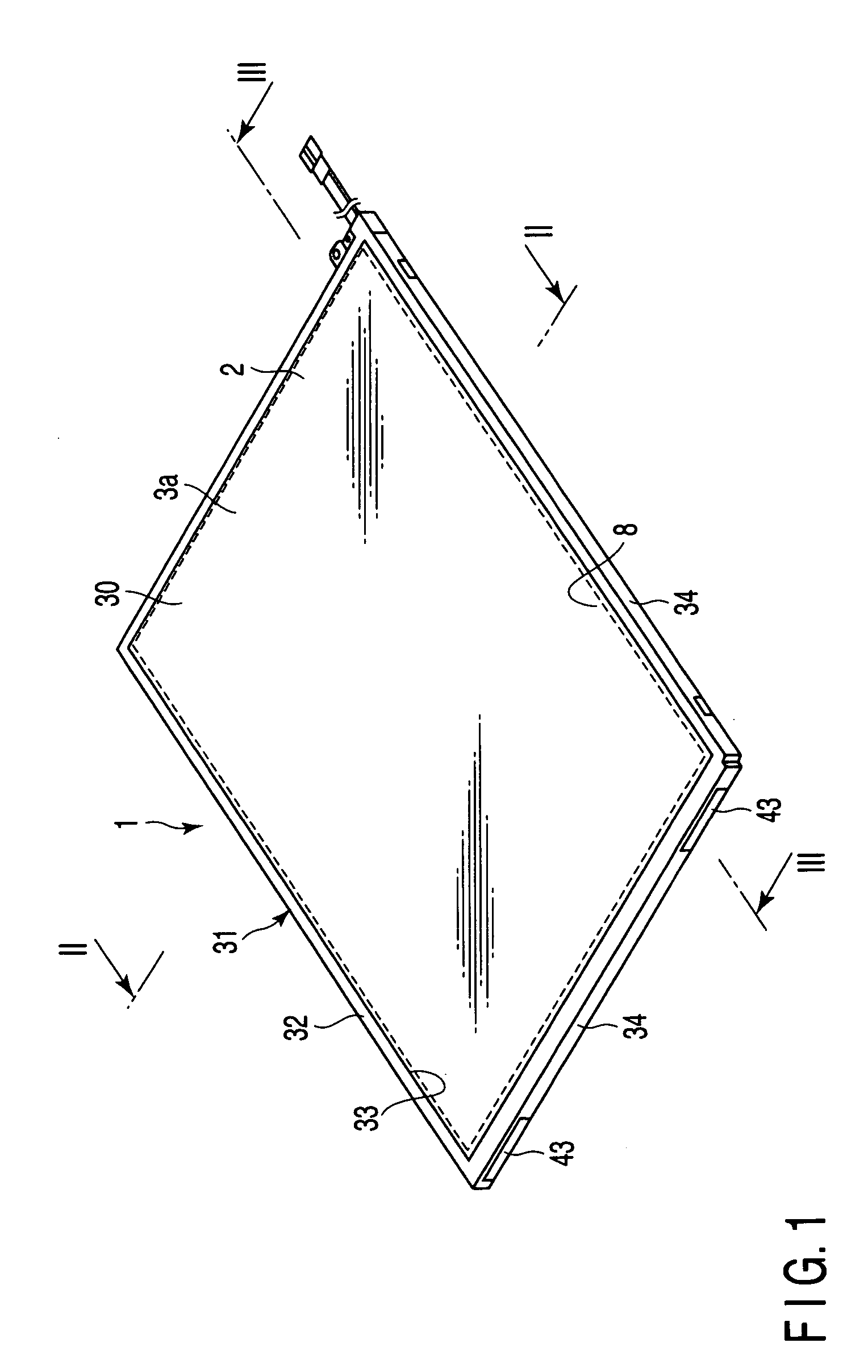
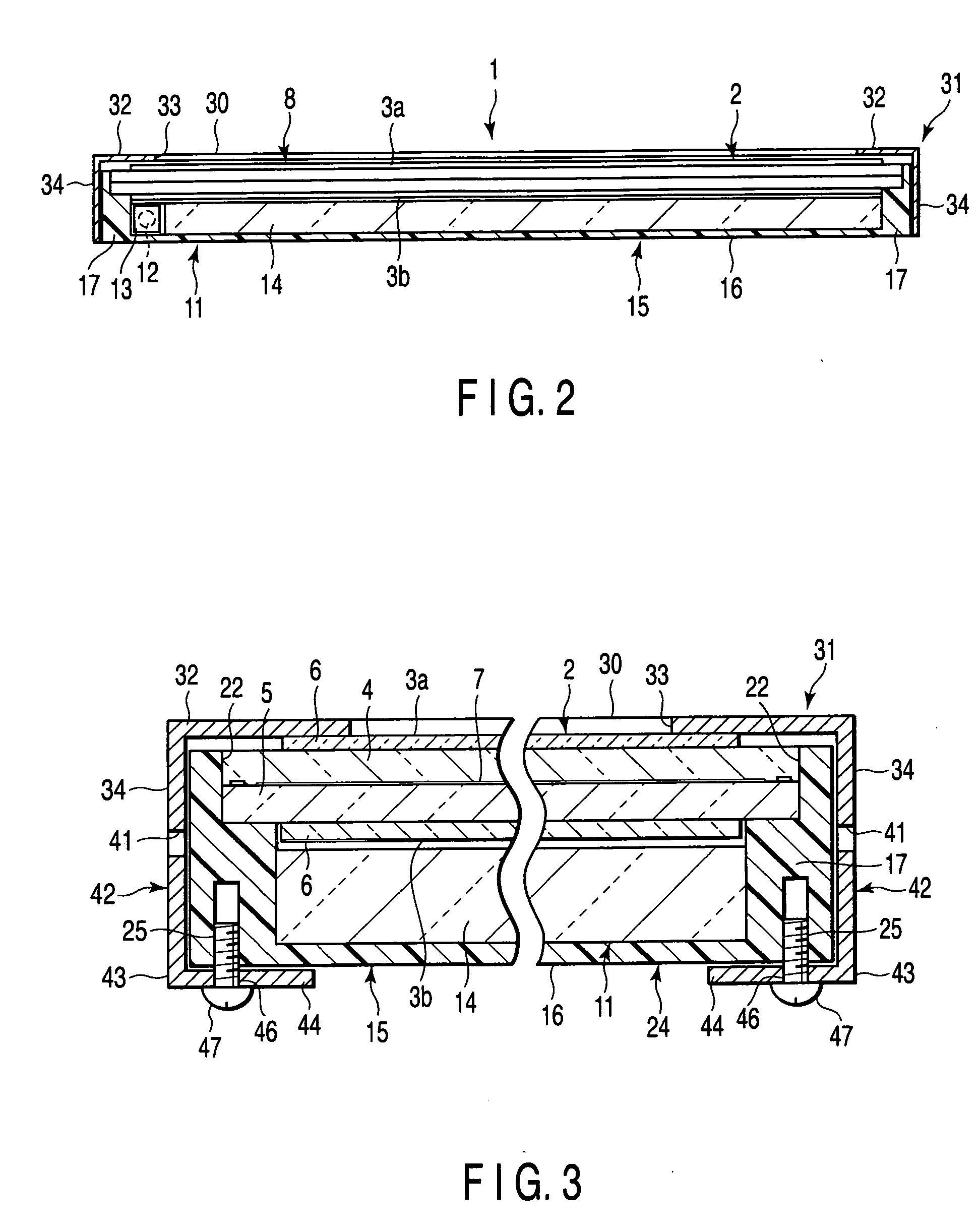
[0027] As shown in FIGS. 1 to 3, a liquid crystal display device 1 comprises a liquid crystal panel 2 in the form of a substantially rectangular sheet that serves as a flat display panel. The liquid crystal panel 2 is transmissive or semi-transmissive. The liquid crystal panel 2 comprises a plurality of thin-film transistors (hereinafter referred to as TFTs), a rectangular array substrate 5 provided with pixel electrodes and the like, and a rectangular opposite substrate 4 opposed to the array board 5. The array substrate 5 and the opposite substrate 4 have their respective peripheral edge portions stuck together and are opposed to each other across a predetermined gap. A liquid crystal layer 7 that serves as a light modulating layer is sealed between the array substrate 5 and the opposite substrate 4. Optical sheets 6 are stuck individually to the outer ...

second embodiment

[0053] Also in the second embodiment, the slit 41 can ease stress in a direction such that the surface portion 32 of the bezel 31 is separated from the liquid crystal panel 2. Accordingly, a gap can be prevented from being formed between the liquid crystal panel 2 and the surface portion 32 of the bezel 31, so that light leakage can be restrained to ensure the liquid crystal display device with improved display quality.

[0054] The following is a description of a liquid crystal display device according to a third embodiment of the present invention. According to the third embodiment, as shown in FIGS. 10 and 11, a reverse portion 44 having a fixed portion is formed of a different member and fixed to a bezel 31.

[0055] Thus, on each short side of the bezel 31, plate members 60 each formed of metal are fixed individually on longitudinally opposite end portions of a side face portion 34. The plate member 60 is provided integrally with a rectangular support portion 62 and a rectangular ex...

third embodiment

[0059] Also in the third embodiment, stress in a direction such that the surface portion 32 of the bezel 31 is separated from the liquid crystal panel 2 can be eased as the plate member 60, which is attached to the bezel 31 in the vicinity of the shortest path C, is elastically deformed. Accordingly, a gap can be prevented from being formed between the liquid crystal panel 2 and the surface portion 32 of the bezel 31, so that light leakage can be restrained to ensure the liquid crystal display device with improved display quality.

[0060] The following is a description of a liquid crystal display device according to a fourth embodiment of the present invention. According to the fourth embodiment, as shown in FIG. 12, a substantially rectangular circuit board 51 is located on the reverse side of a frame 15. The circuit board 51 is connected electrically to a liquid crystal panel 2 and supplies drive signals, such as electrical signals or electrical energy, to the liquid crystal panel 2...


PUM


Abstract

A flat display device includes a display panel, a frame which holds the display panel, and a frame-shaped bezel which is fixed to the frame and holds the display panel on the frame. The bezel has a surface portion, side face portion, reverse portion, fixed portion, and stress easing portion. The surface portion has an end side on the boundary with a display region of the display panel and covers a first main surface of the display panel with the display region exposed. The side face portion covers at least a part of a side face of the frame. The reverse portion extends covering at least a part of a reverse surface of the frame. The fixed portion is provided on the reverse portion and fixed to the frame. The stress easing portion is situated near a shortest path extending from the fixed portion of the bezel toward the end side and eases stress in a direction such that the surface portion and the display panel are separated from each other.

Description

CROSS-REFERENCE TO RELATED APPLICATIONS [0001] This is a Continuation Application of PCT Application No. PCT / JP2004 / 008571, filed Jun. 11, 2004, which was published under PCT Article 21(2) in Japanese. [0002] This application is based upon and claims the benefit of priority from prior Japanese Patent Application No. 2003-169914, filed Jun. 13, 2003, the entire contents of which are incorporated herein by reference.BACKGROUND OF THE INVENTION [0003] 1. Field of the Invention [0004] The present invention relates to a flat display device provided with a flat display panel having a display region for image display on one main surface side. [0005] 2. Description of the Related Art [0006] In recent years, flat display devices represented by liquid crystal display devices have been used as various display devices of TV sets, computers, car navigation systems, etc., taking advantage of their features, such as thinness, lightness in weight, and low power consumption. [0007] As is described i...

Claims


Application Information

Patent Timeline
IPC IPC(8): G06F1/16H05K7/00G02F1/13
CPCG02F2201/46G02F1/133308G02F1/1333G09F9/00
Inventor TSUKAMOTO, TAKAYOSHI
Owner TOSHIBA MATSUSHITA DISPLAY TECH
Why Eureka
Try Eureka