Public key encryption apparatus

a public key and encryption technology, applied in the field of public key encryption apparatus, can solve problems such as difficulty in solving problems, difficulty in obtaining the decryption key from the encryption key, and public key encryption method requiring no safe communication channel

Inactive Publication Date: 2006-04-27
TOSHIBA SOLUTIONS
View PDF4 Cites 66 Cited by
  • Summary
  • Abstract
  • Description
  • Claims
  • Application Information

AI Technical Summary

Benefits of technology

[0013] It is an object of the present invention to provide a public key encryption apparatus capable of realizing a public key encryption method which can guarantee security on the basis of the uncertainty principle, is safe from quantum-computer-based attacks, and can be practiced in the present state of the art.

Problems solved by technology

In the public key encryption method, however, it has to be very difficult to obtain the decryption key from the encryption key.
In contrast, the public key encryption method requires no safe communication channel for key distribution, as long as there is a valid public key.
This type of public key encryption method is generally configured using a mathematical problem expected to have calculation amount difficulty.
Here, “calculation amount difficulty” means difficulty in solving a problem because the amount of calculations to be done is enormous.
However, the expectation that there is calculation amount difficulty has not been proved definitely, but is an assumption.
However, even if a new public key encryption method has been obtained, the grounds for security might collapse, unless calculation amount difficulty has been proved definitely.
Therefore, even if a new public key encryption has been obtained, this hasn't basically guaranteed its security.
However, the aforementioned quantum cryptography is limited in function to key distribution and falls short of the realization of a public key encryption method practicable in the present state of the art.

Method used


Image

  • Public key encryption apparatus
  • Public key encryption apparatus
  • Public key encryption apparatus

Examples


first embodiment

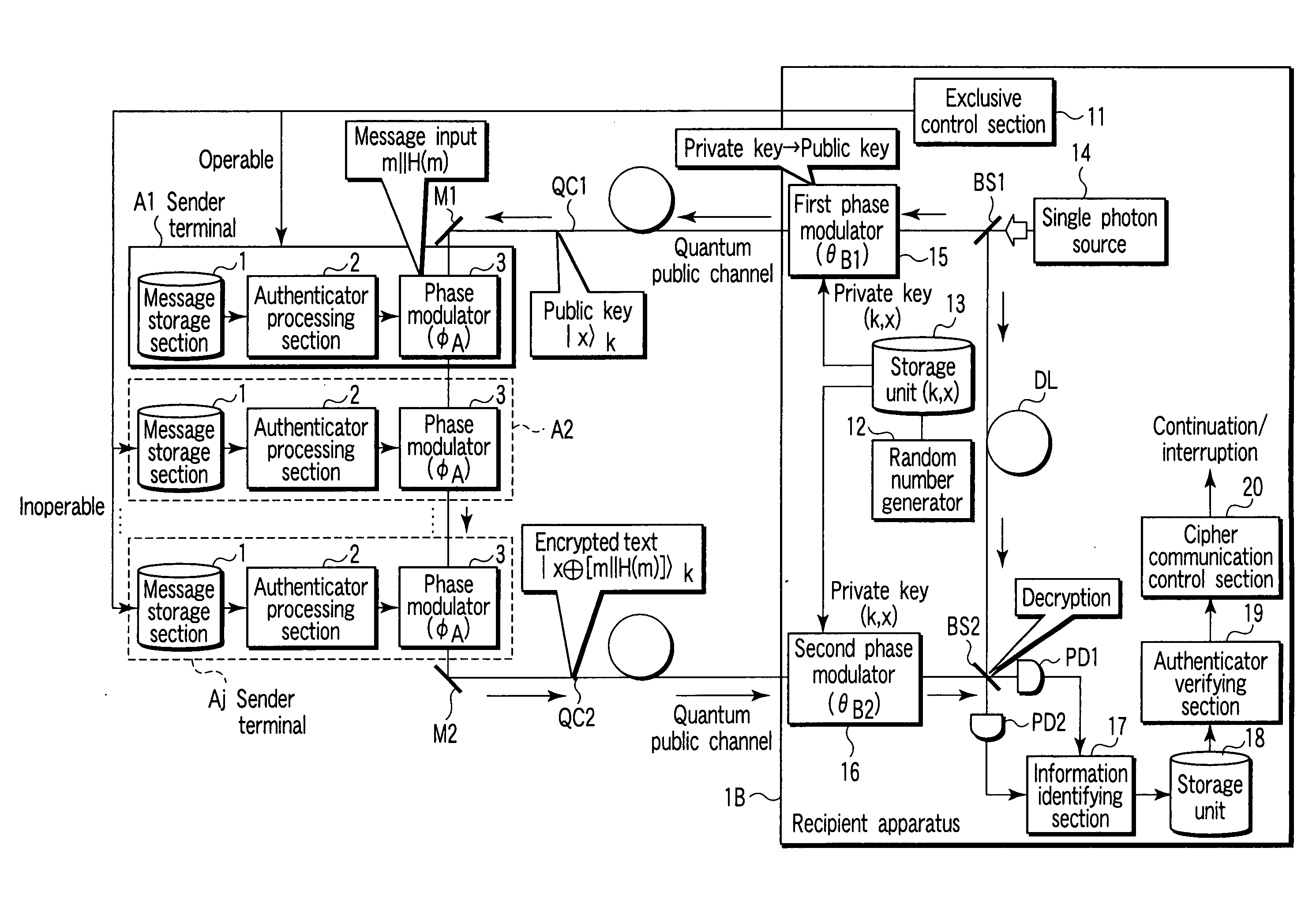
[0063]FIG. 1 is a schematic diagram showing the configuration of a public key encryption apparatus according to a first embodiment of the present invention. In the public key encryption apparatus, a j number of sender terminals A1 to Aj and a single recipient apparatus 1B are connected to one another via quantum public channels QC1, QC2.

[0064] Each of the sender terminals A1 to Aj has a message storage section 1, an authenticator processing section 2, and a phase modulator 3.

[0065] The message storage section 1 stores message information.

[0066] The authenticator processing section 2 has the function of creating an authenticator from the message information in the message storage section 1 and concatenating the authenticator to the message information.

[0067] The phase modulator (a third phase modulation device) 3 has the function of inverting the phase of the public key quantum state, while mainlining the basis set of the public key quantum state output from the recipient apparat...

second embodiment

[0105]FIG. 6 is a schematic diagram showing the configuration of a public key encryption apparatus according to a second embodiment of the present invention. The same parts as those in FIG. 1 are indicated by the same reference numerals and a detailed explanation of them will be omitted. The parts differing from those in FIG. 1 will be mainly explained. Similarly, in the embodiments explained below, a repeated explanation will be omitted.

[0106] The second embodiment, which is a modification of the first embodiment, simplifies the configuration of the first embodiment. Specifically, the second embodiment is so configured that the second phase modulator 16 of FIG. 1 is removed and the first phase modulator 15 is placed between the first beam splitter BS1 and the single photon source 14.

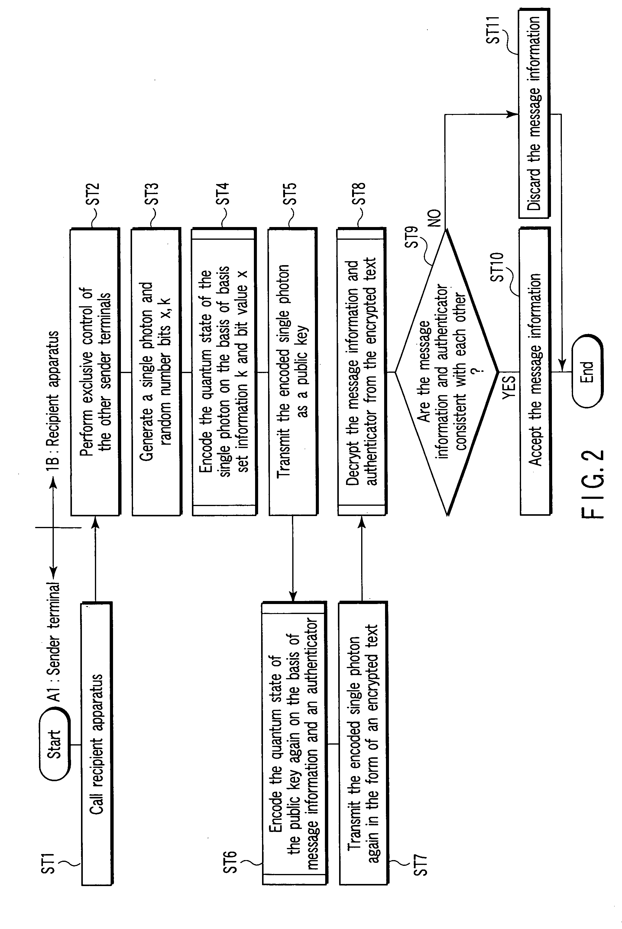
[0107] Next, the operation of the public key encryption apparatus configured as described above will be explained using a flowchart in FIG. 2.

[0108] First, as described above, the recipient apparatus...

third embodiment

[0119]FIG. 9 is a schematic diagram showing the configuration of a public key encryption apparatus according to a third embodiment of the present invention.

[0120] The third embodiment, which is a modification of the first embodiment, performs encoding in ST4 and ST6 of FIG. 2 by the rotation of the polarization component, not by a phase delay. Specifically, a recipient apparatus 3B has a first and a second polarization rotator 21, 22 in place of the first and second phase modulators 15, 16. Sender terminals A1′ to Aj′ each has a polarization rotator 4 in place of the phase modulator 3. In the recipient apparatus 3B, the first beam splitter BS1 and delay line DL are eliminated. In the recipient apparatus 3B, a polarizing beam splitter PBS is provided in place of the second beam splitter BS2.

[0121] Here, on the basis of each bit value of the message information and authenticator concatenated by the authenticator processing section 2, the polarization rotator 4 rotates the polarizati...


PUM


Abstract

According to an aspect of this invention, there is provided a public key encryption apparatus comprising a device generating a single photon, a device generating a random number, a storage device storing the random number as a private key, a device which transmits a single photon encoded by the private key composed of a basis set identifying value section and a bit value section, a device receiving the single photon, a device creating message information and an authenticator, a device encrypting the quantum state of the received single photon on the basis of the message information and authenticator and transmitting the single photon, a device decrypting the message information and authenticator from the received single photon according to the private key, and a device which invalidates the message information if the authenticator calculated from the decrypted message information is inconsistent with the decrypted authenticator.

Description

CROSS-REFERENCE TO RELATED APPLICATIONS [0001] This application is based upon and claims the benefit of priority from prior Japanese Patent Application No. 2004-308655, filed Oct. 22, 2004, the entire contents of which are incorporated herein by reference. BACKGROUND OF THE INVENTION [0002] This invention relates to a public key encryption apparatus capable of realizing a public key encryption method which can assure security on the basis of the uncertainty principle, is safe from quantum-computer-based attacks, and can be practiced in the present state of the art.[0003] In the public key encryption method, a key used in encryption differs from a key used in decryption. Such a public key encryption method was devised by Diffie and Hellman in 1976 (refer to W. Diffie and M. Hellman, “New directions in cryptography,” IEEE Trans. Inf. Theory, IT-22(6), 1976, pp. 644-654). In the public key encryption method, an encryption key is opened to the public and a decryption key is concealed. T...

Claims


Application Information

Patent Timeline
Patent Type & Authority Applications(United States)
IPC IPC(8): H04L9/30
CPCH04L9/0858H04L9/3006H04L9/3226
Inventor FUJII, MIKIO
Owner TOSHIBA SOLUTIONS
Why Eureka
Try Eureka