Supercharge Your Innovation With Domain-Expert AI Agents!

Fluid storage and dispensing system including dynamic fluid monitoring of fluid storage and dispensing vessel

a technology applied in the field of fluid storage and dispensing system, can solve the problems of insufficient or otherwise inefficient and unstandardized time required to navigate the software screen in this implementation, and the majority of ion implant operators and technicians cannot understand the conversion mathematics required

Active Publication Date: 2006-04-27
ENTEGRIS INC
View PDF38 Cites 29 Cited by
  • Summary
  • Abstract
  • Description
  • Claims
  • Application Information

AI Technical Summary

Benefits of technology

The patent describes a new invention and its technical effects. The technical effects of the invention will be explained in detail in the following disclosure and appended claims.

Problems solved by technology

The technical problem addressed in this patent text is the need for a fast, accurate, and reliable approach to monitoring the utilization of fluid storage and dispensing systems in semiconductor manufacturing facilities. Existing approaches are poor, resulting in inefficient and unstandardized gas monitoring techniques that require excessive time and effort to navigate software files and convert pressure readings into meaningful utilization expressions. Additionally, there is a lack of predictability in alerting fab personnel to the approaching end-point of the dispensing operation, which can result in unscheduled shutdowns and reduced efficiency of the fluid storage and dispensing system.

Method used


Image

  • Fluid storage and dispensing system including dynamic fluid monitoring of fluid storage and dispensing vessel
  • Fluid storage and dispensing system including dynamic fluid monitoring of fluid storage and dispensing vessel

Examples


example

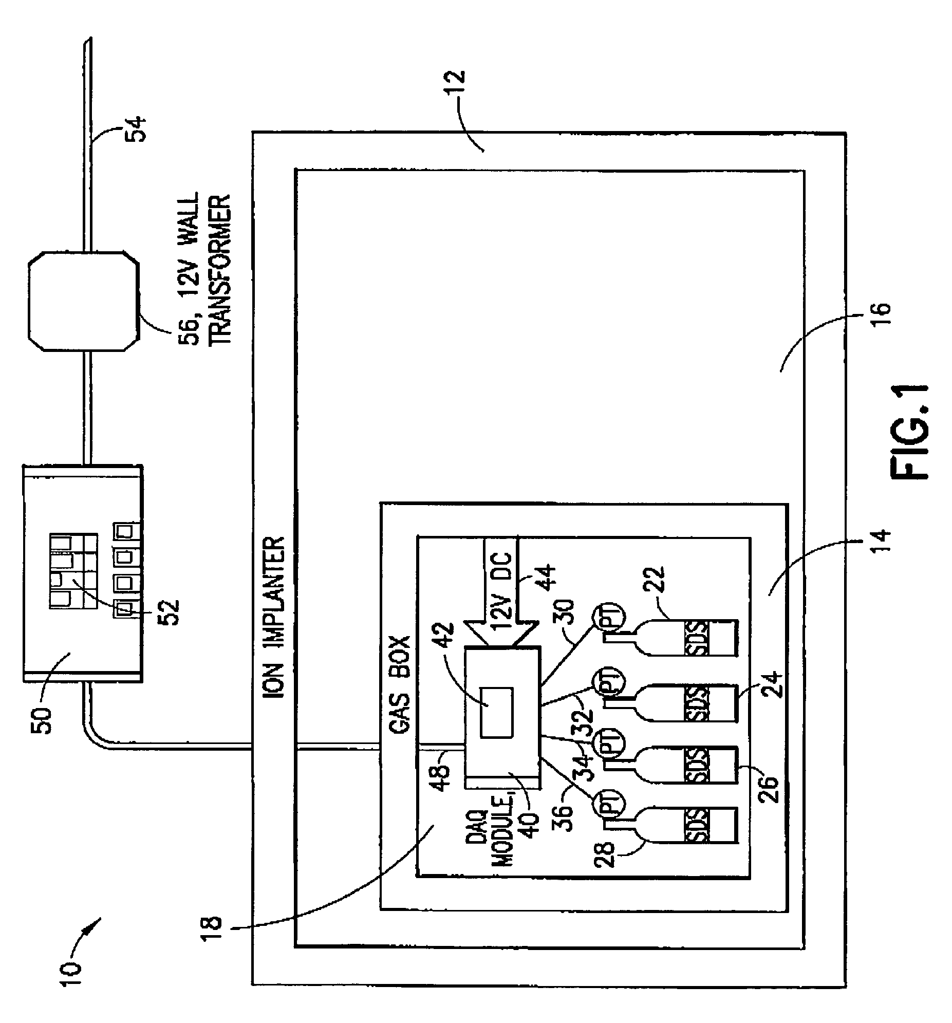
[0052] This example illustrates the procedures used to estimate the usable gas in a gas storage and dispensing system of a type commercially available under the trademark SDS2 from ATMI, Inc. (Danbury, Conn.) and more fully described in U.S. Pat. Nos. 5,518,528; 5,704,965; 5,704,967; and 5,707,424. Such gas storage and dispensing system includes a gas storage and dispensing vessel containing a bead activated carbon adsorbent having sorptive affinity for the semiconductor manufacturing gas held in the interior volume of the vessel. The gas may be of any suitable type, e.g., arsine, phosphine, boron trifluoride, germanium tetrafluoride, and silicon tetrafluoride, and the gas may be retained in the vessel for dispensing therefrom at suitable pressure, e.g., a subatmospheric pressure in a range of 200 to 700 torr.

[0053] The illustrative gas storage and dispensing system is deployed in an ion implanter of the type schematically shown in FIG. 1 hereof, equipped with a dynamic fluid utili...


PUM

PropertyMeasurementUnit
Temperatureaaaaaaaaaa
Pressureaaaaaaaaaa
Concentrationaaaaaaaaaa

Abstract

A monitoring system for monitoring fluid in a fluid supply vessel during operation including dispensing of fluid from the fluid supply vessel. The monitoring system includes (i) one or more sensors for monitoring a characteristic of the fluid supply vessel or the fluid dispensed therefrom, (ii) a data acquisition module operatively coupled to the one or more sensors to receive monitoring data therefrom and responsively generate an output correlative to the characteristic monitored by the one or more sensors, and (iii) a processor and display operatively coupled with the data acquisition module and arranged to process the output from the data acquisition module and responsively output a graphical representation of fluid in the fluid supply vessel.

Description


Claims


Application Information

Patent Timeline
Owner ENTEGRIS INC
Features
  • R&D
  • Intellectual Property
  • Life Sciences
  • Materials
  • Tech Scout
  • Unparalleled Data Quality
  • Higher Quality Content
  • 60% Fewer Hallucinations
Learn More