Fiber optic industrial connector

Active Publication Date: 2006-04-27
PANDUIT
View PDF21 Cites 230 Cited by
  • Summary
  • Abstract
  • Description
  • Claims
  • Application Information

AI Technical Summary

Benefits of technology

[0004] It would be desirable to provide an LC fiber optic industrial connector that allows simple removal of the LC connectors during or after termination.

Problems solved by technology

Moreover, none of these prior art industrial connectors disclose an LC fiber optic industrial connector that allows simple removal of the LC connectors during or after termination.

Method used


Image

  • Fiber optic industrial connector
  • Fiber optic industrial connector
  • Fiber optic industrial connector

Examples


Embodiment Construction

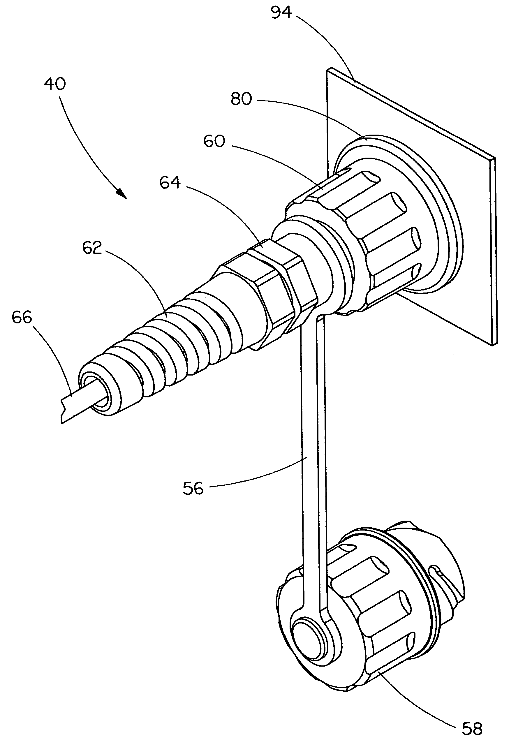
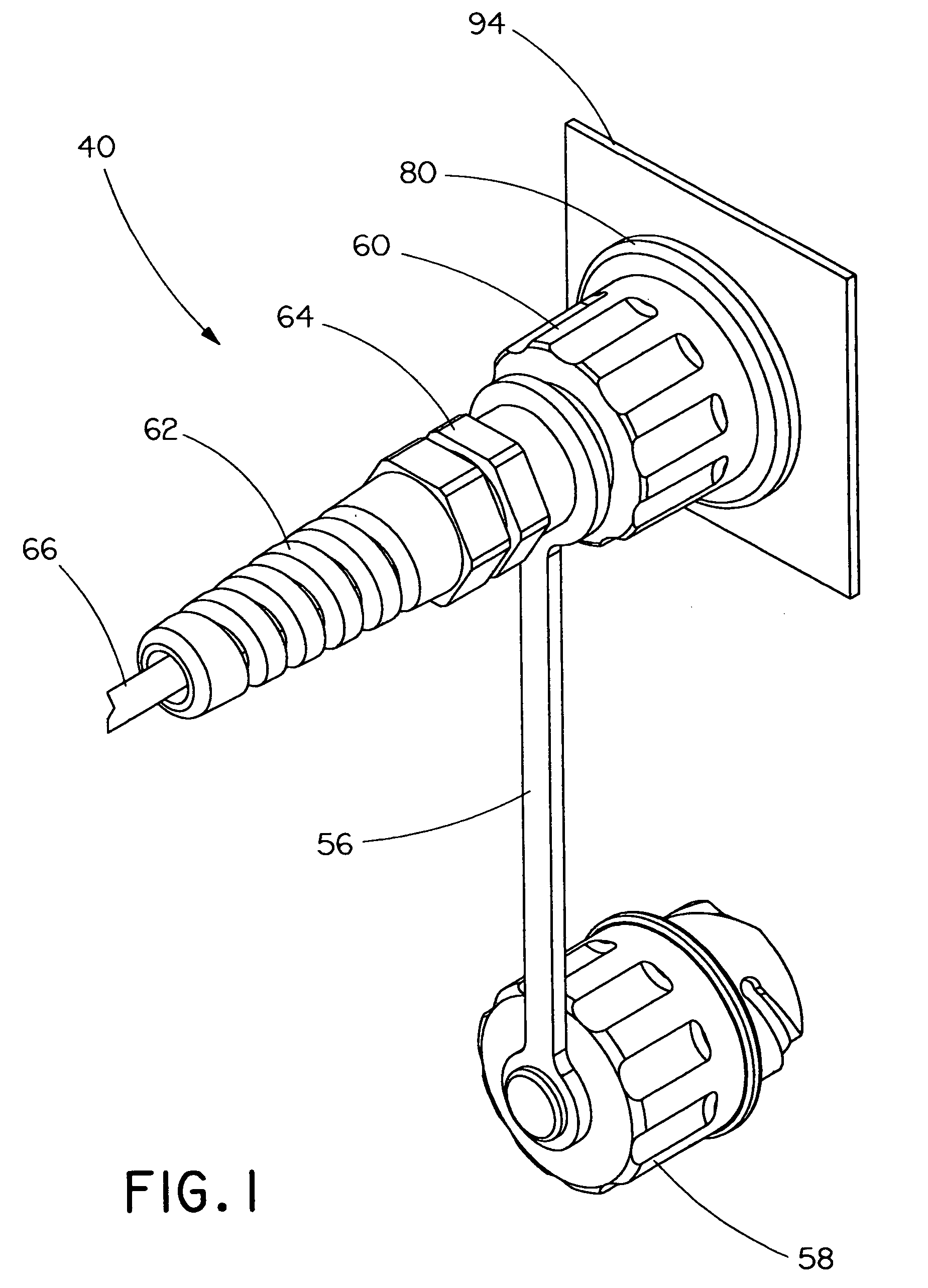
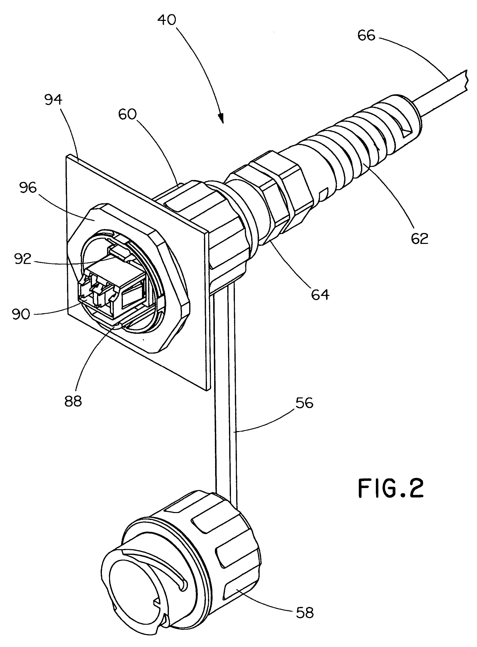
[0042]FIGS. 1-31 illustrate an LC fiber optic industrial connector 40. It is likewise contemplated that other fiber optic style connectors, such as an SC or an ST style connector, may be utilized. FIG. 3 shows an exploded view of the components of industrial connector 40. FIGS. 28 and 29 show an assembled plug-side 42 of industrial connector 40, and FIGS. 30 and 31 show an assembled bulkhead-side 44 of industrial connector 40.

[0043] Referring to FIG. 3, in order to assemble plug-side 42 of industrial connector 40, plug sealing gasket 46 and 0-ring 48 are first installed onto the front and rear sides of LC connector holder 50, respectively, creating an LC connector holder assembly. Plug face seal 54 and plug tether 56 are then installed onto plug cap 58, creating a plug cap assembly. Flexible boot 62, liquid-tight fitting 64 and the plug cap assembly are slid onto fiber cable 66. Plug collar 60, the LC connector holder assembly and crimp sleeves 68 are subsequently slid onto fiber c...


PUM


Abstract

A fiber optic industrial connector includes a connector holder and a duplex clip assembly secured within the connector holder. The duplex clip assembly includes a duplex clip and two connectors secured within the duplex clip. The duplex clip has a front surface and a rear surface, and two openings positioned between the front surface and the rear surface. The duplex clip also has a projecting member extending from the rear surface and toward the front surface.

Description

CROSS-REFERENCE TO RELATED APPLICATIONS [0001] This application claims priority to U.S. Provisional Application Ser. No. 60 / 622,636, filed on Oct. 27, 2004, the entirety of which is incorporated herein by reference.BACKGROUND OF THE INVENTION [0002] The present invention is directed to a fiber optic industrial connector and, more particularly, an LC fiber optic industrial connector. [0003] Industrial telecommunication connectors are known in the art, as shown and described in U.S. Pat. Nos. 6,475,009 and 6,595,791. The '009 and '791 patents disclose RJ-45 connectors, which do not include duplex clip and connector assemblies. Moreover, none of these prior art industrial connectors disclose an LC fiber optic industrial connector that allows simple removal of the LC connectors during or after termination. SUMMARY OF THE INVENTION [0004] It would be desirable to provide an LC fiber optic industrial connector that allows simple removal of the LC connectors during or after termination. [0...

Claims


Application Information

Patent Timeline
IPC IPC(8): H01R13/66
CPCG02B6/3849G02B6/3879G02B6/3887G02B6/3897G02B6/3891G02B6/3893G02B6/3894G02B6/3888
Inventor SEDOR, THOMAS M.
Owner PANDUIT
Why Eureka
Try Eureka