Video storage system

a video storage and video technology, applied in the field of video storage systems, can solve the problems of increasing installation costs, inability to use pull mode and achieve the effects of increasing the scale of the system, low cost, and high cost of protecting video storag

Active Publication Date: 2006-04-27
RAKUTEN GRP INC
View PDF14 Cites 27 Cited by
  • Summary
  • Abstract
  • Description
  • Claims
  • Application Information

AI Technical Summary

Benefits of technology

[0012] In the conventional technologies described above, the camera eventually sends the store-request to the video storage system, and a video is sent to video storage using the store-request path. Therefore, it is usually not possible to use the PULL mode, which enables the protection of video storage at a low cost, and the cost for protecting video storage is comparably high. Further, with an increase in the scale of the system, the number of video storage modules and the number of protection devices provided in the respective video storage modules are increased resulting in increased installation cost.

Problems solved by technology

Therefore, it is usually not possible to use the PULL mode, which enables the protection of video storage at a low cost, and the cost for protecting video storage is comparably high.
Further, with an increase in the scale of the system, the number of video storage modules and the number of protection devices provided in the respective video storage modules are increased resulting in increased installation cost.

Method used


Image

  • Video storage system
  • Video storage system
  • Video storage system

Examples


first embodiment

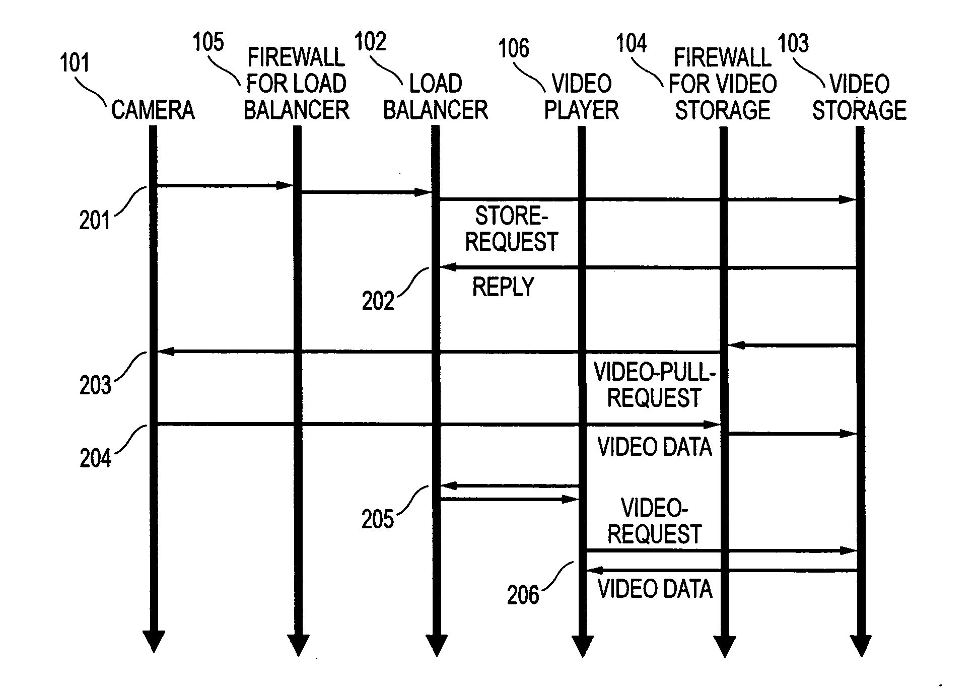
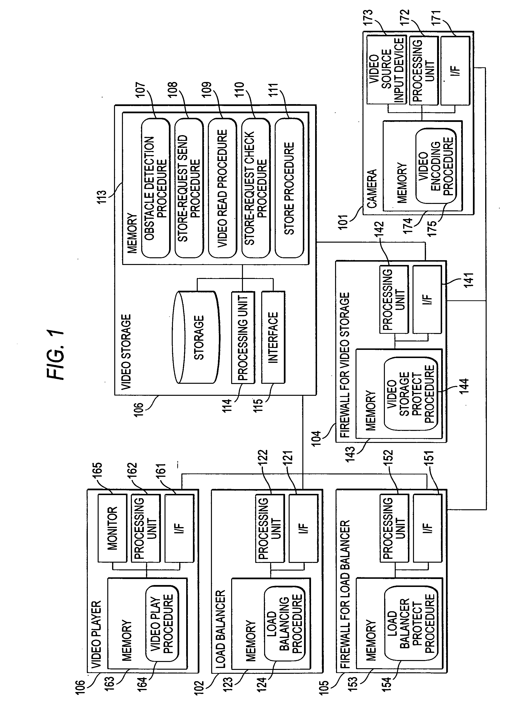
[0027]FIG. 1 illustrates a system configuration of the first embodiment. The system includes multiple cameras 101, a load balancer 102, a video storage module 103, a video player 106, a firewall 104 for video storage 103, and a firewall 105 for load balancer 102. Video player 106 is a terminal device having a monitor for displaying video. In one implementation, in a building monitoring system, the load balancer 102, video storage 103, video player 106, and firewalls 104 and 105 are installed in a monitoring room, while cameras 101 are installed in the respective floors of the building to be monitored.

[0028] Each of the cameras 101 includes an interface 171, a processing unit 172, a video source input device 173, and a memory 174. Memory 174 stores a video encoding procedure program 175. Within camera 101, processing unit 172 packetizes video received from video source input device 173 by executing a video encoding procedure program 175 to send packets to a network via interface 171...

second embodiment

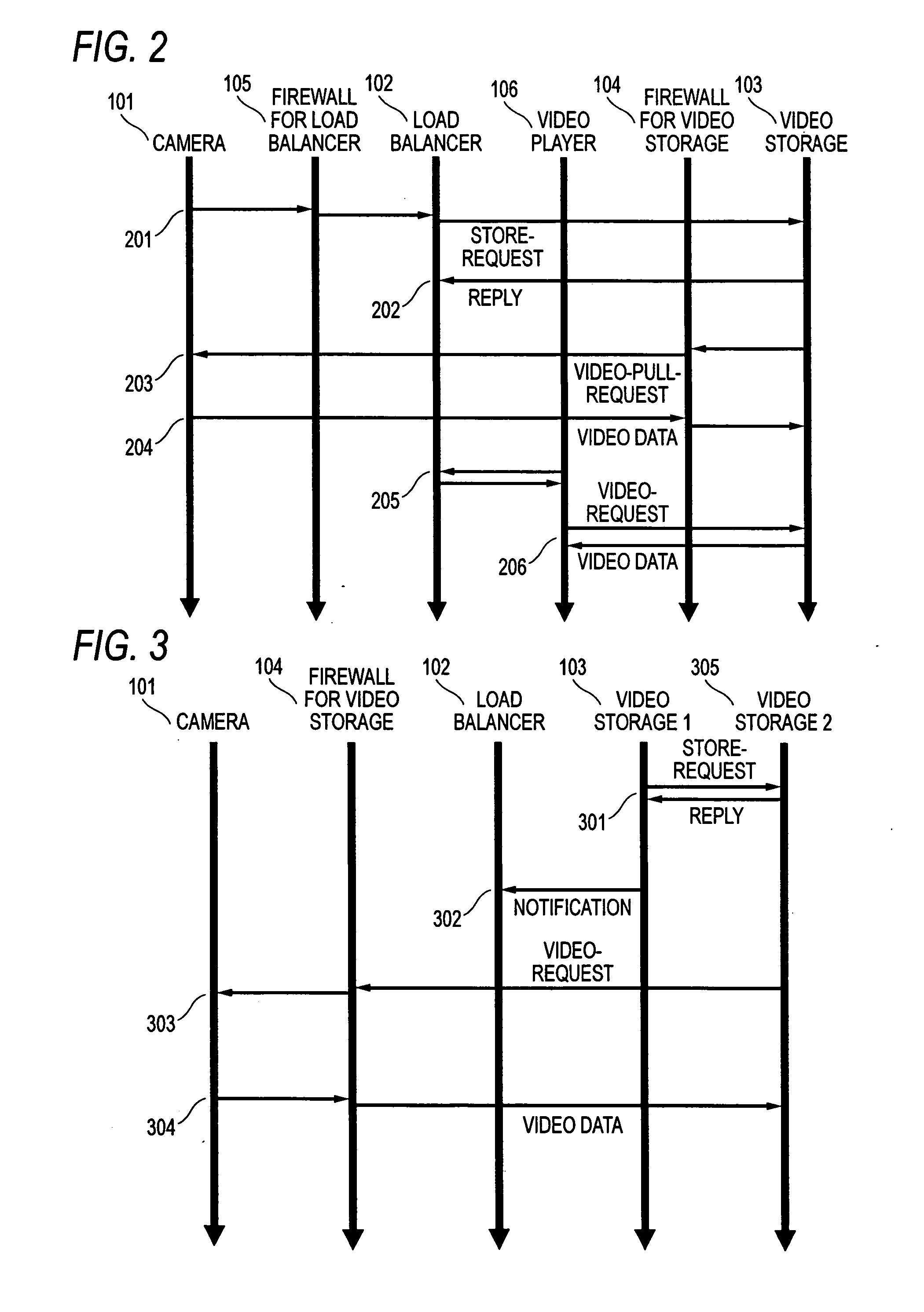
[0057] In this embodiment, a system different from that described as the prerequisite in the foregoing description is described. In the first embodiment, the PULL mode is used as the method of sending / receiving video data and a store-request from a camera is pushed to a load balancer. However, it is possible to use not only the PULL mode but also the PUSH mode as the method for sending / receiving video data. Moreover, since it is possible to select the PUSH mode or the PULL mode for sending a store-request from a camera in addition to the above-mentioned video data sending / receiving methods, four embodiments can be made by combining the methods. An example of using the PUSH mode for sending / receiving video data and the PULL mode for sending / receiving store-request is now described to prove feasibility of the four embodiments.

[0058] An overall operation procedure is described with reference to FIG. 12. First, a video data sending / receiving method using the PUSH mode is explained, and...


PUM


Abstract

Control data, such as a store-request, and video data are sent via different paths to video storage. More specifically, a load balancer sends the control data from a camera to the storage device, and the camera sends the video data to video storage. By separating the transmission paths of the control data and the video data, it is possible to vary the method for protecting the video storage, depending on the type of data, and to intensively check the control data which are smaller in data quantity, thereby realizing both a high security level and a cost reduction for protecting video storage.

Description

[0001] CROSS-REFERENCE TO RELATED APPLICATION [0002] This application relates to and claims priority from Japanese Patent Application No. 2004-+307584, filed on Oct. 22, 2004, the entire disclosure of which is incorporated herein by reference.BACKGROUND OF THE INVENTION [0003] 1. Field of the Invention [0004] The present invention relates to a tchnology for storing videos. [0005] 2. Description of Related Art [0006] Recently, a format for storing video content, such as security camera footage and live video, has changed to a digital format which does not have the image degradation fo an analog format. With the shift to digital format, there is increased interest in technology for storing video in a system connected to a network. Requirements and needs for video storage technology vary form small-scale video storage technology for room monitoring and the like, to large-scale video storage technology for wide area monitoring, such monitoring a city, or monitoring river traffic [0007] ...

Claims


Application Information

Patent Timeline
Patent Type & Authority Applications(United States)
IPC IPC(8): G06F15/177G06F3/06G06F12/00G06F13/00H04N7/173H04N7/18H04N21/2743H04N21/61H04N21/81
CPCH04L12/2838H04L2012/2849H04N21/43615H04L67/1002H04L67/1017H04L67/1001
Inventor NOMURA, KEN
Owner RAKUTEN GRP INC
Why Eureka
Try Eureka