Supercharge Your Innovation With Domain-Expert AI Agents!

Storage system and storage control device

Inactive Publication Date: 2006-04-27
HITACHI LTD
View PDF99 Cites 56 Cited by
  • Summary
  • Abstract
  • Description
  • Claims
  • Application Information

AI Technical Summary

Benefits of technology

[0016] In an embodiment of the present invention, the first storage control device has a first storage device, and the second storage control device has a second storage device; furthermore, the first real volume is connected to the first storage device via an intermediate storage device, and the first virtual volume is connected to the second storage device via a virtually constructed virtual intermediate storage device. Here, the intermediate storage device is a storage hierarchy which logically connects the first storage device that provides a physical storage region, and the first virtual volume. Similarly, the virtual intermediate storage device is a storage hierarchy which logically connects the second storage device that provides a physical storage region, and the first virtual volume. Furthermore, while the intermediate storage device is set in the storage region of the of the first storage device of the first storage control device, the virtual intermediate storage device is associated with the storage region of the second storage device of the second storage control device. Specifically, by mapping the second storage device in the virtual intermediate storage device, it is possible to vary the storage capacity, or to employ a stripe structure or the like.
[0022] By starting differential copying after setting the access attribute of the volume as “write prohibited”, it is possible to prohibit updating requests (write requests) from the higher device, and to match the storage contents of the copying source volume (the first real volume in this case) and the copying destination volume (the first virtual volume in this case). Furthermore, since it is sufficient to alter only the access attribute inside the storage control device without any need to alter the setting of the higher device, data matching can be ensured by means of comparatively simple construction.
[0024] Furthermore, in cases where write requests to the second real volume from the higher device are prohibited, the synchronizing part can maintain the matching of data by copying the differential data into the first real volume.

Problems solved by technology

In cases where a complete transition is made from an old type of storage control device to a new type of storage control device, the function and performance of the new type of storage control device can be utilized; however, the old type of storage control device cannot be effectively utilized, and the introduction costs are also increased.
On the other hand, in cases where an old type of storage control device and a new type of storage control device are used together, the number of storage control devices that construct the storage system is increased, and considerable effort is required in order to control and operate both the new and old storage control devices.
Furthermore, in cases where the response of the storage device in which the old type of storage control device is installed is slow, the performance of the overall system drops as a result of this old type of storage control device being connected to the storage system.
Furthermore, there may also be cases in which an old type of storage device cannot be utilized “as is”, as in combinations of open type storage devices and main frames, or servers to which only storage devices with specified functions can be connected.

Method used


Image

  • Storage system and storage control device
  • Storage system and storage control device
  • Storage system and storage control device

Examples


first embodiment

1. First Embodiment

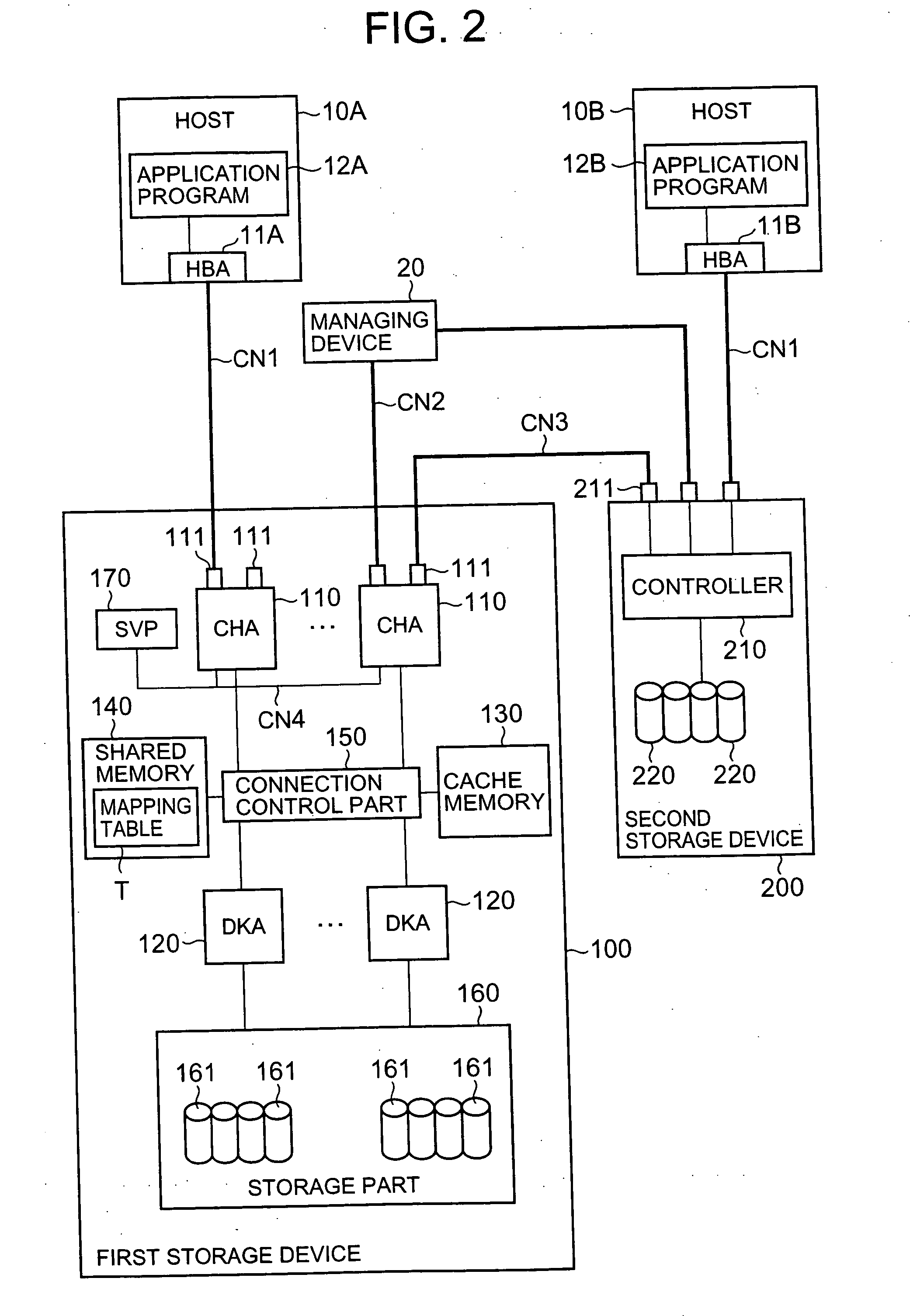
[0057]FIG. 2 is a block diagram which shows the construction of the essential parts of the storage system of the present embodiment. For example, the hosts 10A and 10B are computer devices comprising information processing resources such as a CPU (central processing unit), memory and the like; for instance, these hosts are constructed as personal computers, workstations, main frames or the like.

[0058] The host 10A comprises an HBA (host bus adapter) 11A that is used to access a first storage device 100 via a communications network CN1, and (for example) an application program 12A such as data base software or the like. Similarly, the host 10B also comprises an HBA 11B that is used to access a second storage device 200, and an application program 12B. Below, in cases where no particular distinction is made between the respective hosts 10A and 10B, these parts will be referred to simply as hosts 10, HBA 11 and application programs 12.

[0059] For example, depending ...

second embodiment

2. Second Embodiment

[0165] A second embodiment of the present invention will be described with reference to FIG. 17. The following embodiments including this embodiment correspond to modifications of the abovementioned first embodiment. In the present embodiment, copying is performed among a plurality of virtual internal volumes inside the first storage device 100. Furthermore, in the present embodiment, the first storage device 100 does not comprise any internal volumes. FIG. 17 is an explanatory diagram showing the storage structure of a storage system constituting a second embodiment of the present invention.

[0166] In the present embodiment, the first storage device 100 comprises a third storage device 300 in addition to a second storage device 200. Like the second storage device 200, this third storage device 300 is a device that is externally connected to the first storage device 100. Like the second storage device 200, the third storage device 300 comprises (for example) PDEV...

third embodiment

3. Third Embodiment

[0170] A third embodiment will be described with reference to FIG. 18. FIG. 18 is an explanatory diagram which shows one example of the control screen used by the storage system. This embodiment can be used in any of the respective embodiments described above.

[0171] For example, in cases where copying pairs are set in the storage system, the user logs into the managing device 20, and calls up a control screen such as that shown in FIG. 18. When the construction of a copying pair or the like is set on this control screen, the managing device 20 sends instructions for alteration of the construction to one or both of the storage devices 100 and 200. Receiving these instructions, the respective storage devices 100 and 200 alter their internal construction.

[0172] A plurality of different types of control menus M1 through M3 can be set on the control screen. For example, these control menus M1 through M3 can be constructed as tab type switching menus. For instance, th...


PUM


Abstract

The present invention makes it possible, by virtualizing an external memory resource as an internal memory resource, to effectively utilize memory resources, and to synchronize the storage contents of a virtualized inner volume and a real inner volume. The first storage device comprises an internal volume and a virtual internal volume. The entity of the virtual internal volume is the external volume of a second storage device. The external volume can be dealt with as a volume inside the first storage device by mapping the external volume in the storage hierarchy of the first storage device. Furthermore, a copying pair can be formed by internal volume and virtual internal volume, and the contents of both volumes can be synchronized.

Description

CROSS-REFERENCE TO RELATED APPLICATION [0001] This application relates to an claims priority from Japanese Patent Application No. 2004-312358 filed on Oct. 27, 2004, the entire disclosure of which is incorporated herein by reference. BACKGROUND OF THE INVENTION [0002] 1. Field of the Invention [0003] The present invention relates to a storage system and a storage control device. [0004] 2. Description of the Related Art [0005] For example, data is controlled using relatively large-scale storage systems in order to handle large quantities of various types of data in government organizations, public offices, autonomous regional bodies, business enterprises, educational organizations and the like. For instance, such storage systems are constructed from disk array devices or the like. Disk array devices are constructed by disposing numerous storage devices in the form of an array; for example, a storage region based on an RAID (redundant array of independent disks) is provided. One or mo...

Claims


Application Information

Patent Timeline
IPC IPC(8): G06F12/10
CPCG06F3/0605G06F3/0607G06F3/065G06F3/0665G06F3/067G06F11/1662G06F11/2071G06F11/2082
Inventor OKUMOTO, KATSUHIRONAKAGAWA, YOSHIHITOHONMA, HISAOTAMURA, KELSHI
Owner HITACHI LTD
Features
  • R&D
  • Intellectual Property
  • Life Sciences
  • Materials
  • Tech Scout
  • Unparalleled Data Quality
  • Higher Quality Content
  • 60% Fewer Hallucinations
Learn More