Tread comprising a ventilated device for countering irregular wear

a technology of treads and ventilated devices, which is applied in the direction of non-skid devices, vehicle components, transportation and packaging, etc., can solve the problems of increasing energy consumption, accelerating the ageing of rubber mixes, and changing the conditions of use, so as to reduce the thermal level and better weather the effect of impa

Inactive Publication Date: 2006-05-04
MICHELIN RECH & TECH SA
View PDF7 Cites 22 Cited by
  • Summary
  • Abstract
  • Description
  • Claims
  • Application Information

AI Technical Summary

Benefits of technology

[0007] The subject of the invention is a tread the structural characteristics of which make it possible to maintain a sacrificed-rib effect preventing the development of irregular wear on the edges of the ribs axially to the outside of the tread, this tread itself being provided with a tread pattern formed of a plurality of grooves of general circumferential orientation defining ribs, this tread when in use having an appropriate, reduced thermal level in order to limit the phenomenon of accelerated ageing of the rubber mixes, and this tread better withstanding impacts against its edges.

Problems solved by technology

This structure has completely demonstrated its effectiveness in use; however, it has been noted that conditions of use have changed substantially and are nowadays more demanding than in the past and that the result is heating within the different rubber mixes of the tread in particular in the vicinity of the axial ends of the reinforcing belt for the crown of the tire and also in the region of the sacrificed rib.
This heating resulting from the mechanical stresses due to the traveling conditions result in an additional energy consumption and are also the cause of accelerated ageing of the rubber mixes and a reduction in the fatigue and tear resistance performance of the rubber mixes in particular under the effect of impacts.
Use of these tires on heavy vehicles traveling in countries of high average temperature is very adversely affected.

Method used


Image

  • Tread comprising a ventilated device for countering irregular wear
  • Tread comprising a ventilated device for countering irregular wear
  • Tread comprising a ventilated device for countering irregular wear

Examples


Embodiment Construction

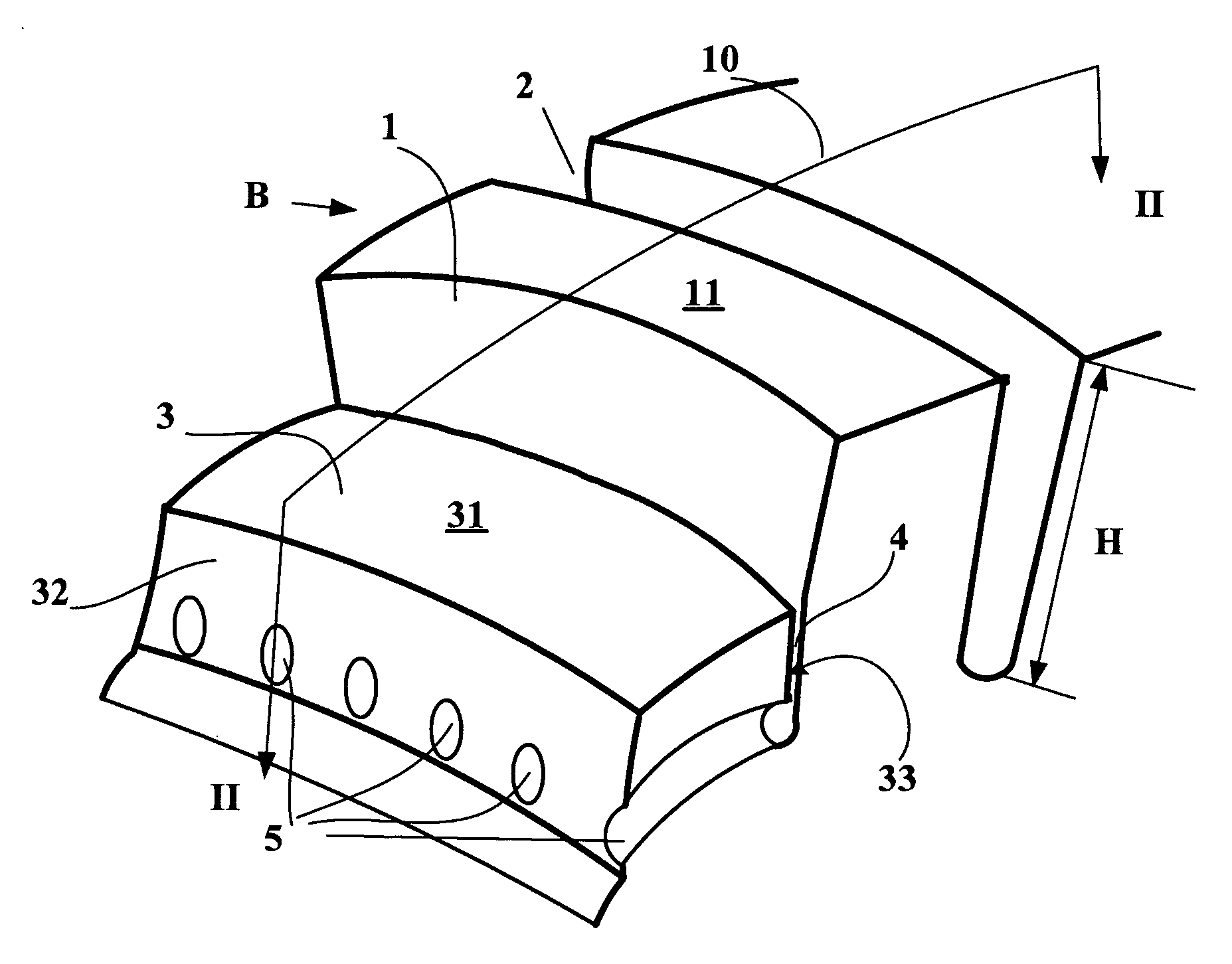
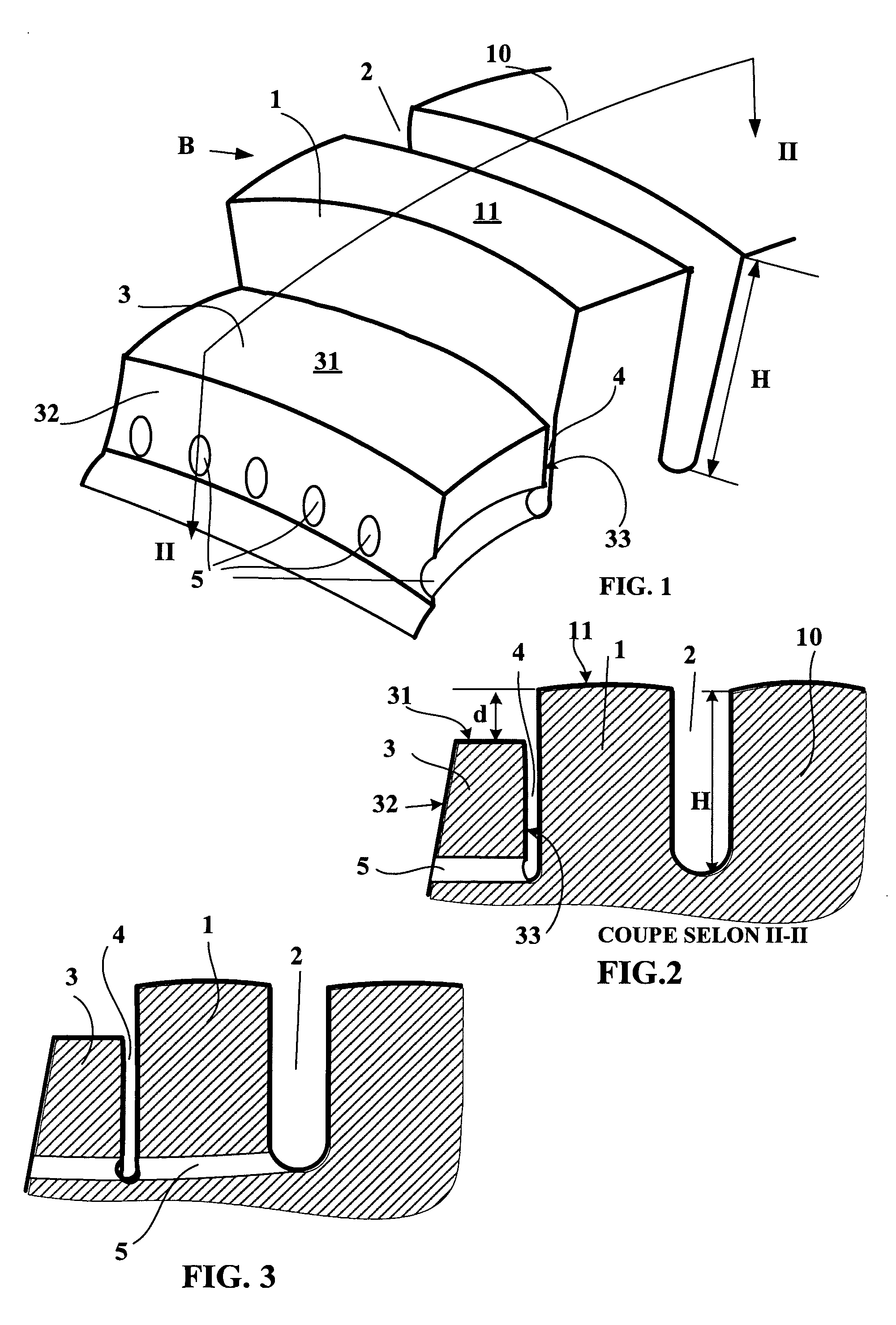
[0023]FIG. 1 shows a local view of a tread B according to the invention, for a tire of dimension 315 / 80 R 22.5, comprising a tread pattern formed by a plurality of main ribs 1, 10 oriented in the circumferential direction, these main ribs 1, 10 being separated from one another by main grooves 2 of circumferential orientation and of depth H and of the same width. FIG. 1 shows an edge of the tread with an edge rib 1 provided axially towards the outside of the tread with an offset rib 3 of a width equal to 7.8 mm, this offset rib 3 being separated from the edge rib by an incision 4 of a width less than 1 mm and having the width of the main grooves 2. This incision 4 is extended in the thickness of the tread to substantially the same depth as the main grooves.

[0024] The offset d, which in the case illustrated is equal to 1.4 mm, between the contact face 11 of the edge rib 1 forming part of the running surface of the tread and the outer face 31 of the offset rib 3 is such that, upon loa...


PUM


Abstract

A tread (B) provided with a tread pattern formed of a plurality of elements in relief (1, 10) which are defined by grooves and/or incisions (2), this tread pattern comprising on each of its edges, that is to say axially furthest to the outside of the tread, an edge rib (1) of circumferential orientation defined axially to the inside by a groove (2) of the same general orientation and of depth H, this tread furthermore comprising, axially to the outside of each edge rib (1), a rib (3) offset relative to the outer contact surface (11) of the neighboring edge rib (1) by a distance d other than zero, this offset rib (3) being separated from the edge rib (1) by a groove (4) of a depth identical or close to the depth H of the groove (2) defining the edge rib (1), wherein the tread comprises, on either side where a sacrificed rib (3) is formed, a plurality of channels (5) opening on to the lateral faces of the tread, these channels (5) being extended in the tread until they open into the groove (4) between the offset rib (3) and the neighboring edge rib (1).

Description

RELATED APPLICATION [0001] This application is a U.S. Continuation Application under 35 USC 371 of International Application PCT / EP2004 / 006335 filed Jun. 11, 2004.FIELD OF THE INVENTION [0002] The subject of the present invention is an improvement to the tread of tires for heavy vehicles; it relates in particular to treads provided with a tread pattern formed of tread pattern elements essentially in the form of ribs or a combination of blocks and ribs. [0003] This invention is more particularly intended to be used for radial-carcass tires intended for the non-driving axles of heavy vehicles. BACKGROUND OF INVENTION [0004] Such tires most frequently comprise a carcass reinforcement surmounted radially to the outside by a crown belt which itself is surmounted by a tread provided with a tread pattern formed essentially of ribs of general circumferential orientation. It is known in particular from U.S. Pat. No. 4,480,671 to provide each of the lateral zones of this tread with a lateral ...

Claims


Application Information

Patent Timeline
Patent Type & Authority Applications(United States)
IPC IPC(8): B60C11/01B60C11/12B60C11/13
CPCB60C11/01B60C11/032B60C11/13B60C2011/013B60C11/0323
Inventor MERINO LOPEZ, JOSE
Owner MICHELIN RECH & TECH SA
Why Eureka
Try Eureka