
Secondary battery module and cooling apparatus for secondary battery module

a secondary battery module and battery module technology, applied in the field of secondary batteries, can solve the problems of battery module malfunction, battery module malfunction, and battery module internal characteristic severely affecting the battery

Inactive Publication Date: 2006-05-04
SAMSUNG SDI CO LTD
View PDF4 Cites 122 Cited by
  • Summary
  • Abstract
  • Description
  • Claims
  • Application Information

AI Technical Summary

Benefits of technology

The present invention relates to a battery module with a housing for accommodating multiple unit cells. The housing has an inflow guide for introducing temperature controlling air and an air outlet for discharging the air. The air inlet has a one-sided inlet hole and the air outlet has a one-sided outlet hole, allowing for uniform air flow through the unit cells. The air inlet and outlet have an air guide side that is inclined towards the unit cells to collect and discharge the air. The cooling system includes a housing with an air ventilator for dissipating heat generated from the unit cells. The technical effects of the invention include improved temperature control and air flow through the unit cells.

Problems solved by technology

If heat is not dissipated properly, the heat generated from the unit cells may induce unacceptable temperature elevation of the battery module.
As a result, the battery module may malfunction.
This severely affects the intrinsic characteristic of the battery, and deteriorates the intrinsic capacity thereof.
Furthermore, the internal pressure of the battery may be elevated due to the internal chemical reaction of the battery, and accordingly, the shape of the battery may become distorted, severely affecting the intrinsic characteristics of the battery.
Particularly when the ratio of the width to the length of the secondary battery is high, as in a prismatic secondary battery, such a risk is increased.
However, with the conventional way of cooling, the amount of cooling air ventilated through respective cell barriers is not uniform, causing a temperature deviation among the unit cells.
Accordingly, with a conventional battery module, the heat generated from the respective unit cells is not dissipated uniformly, deteriorating the charging and discharging efficiency of the battery module.

Method used


Image

  • Secondary battery module and cooling apparatus for secondary battery module
  • Secondary battery module and cooling apparatus for secondary battery module
  • Secondary battery module and cooling apparatus for secondary battery module

Examples


Embodiment Construction

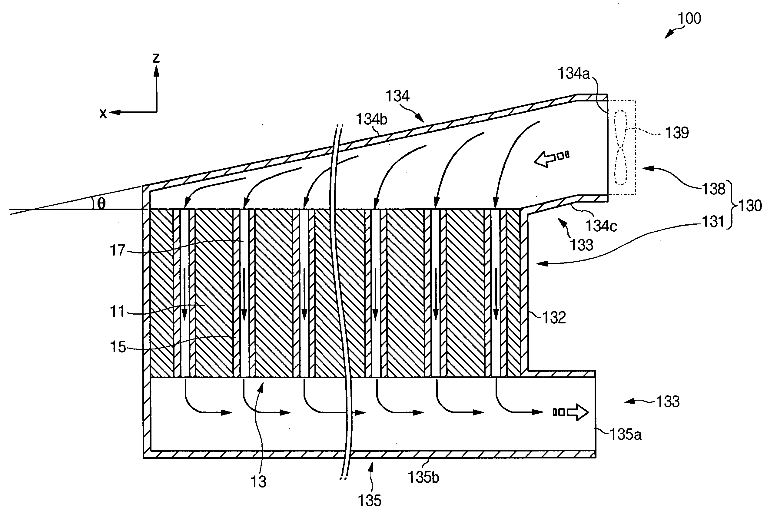
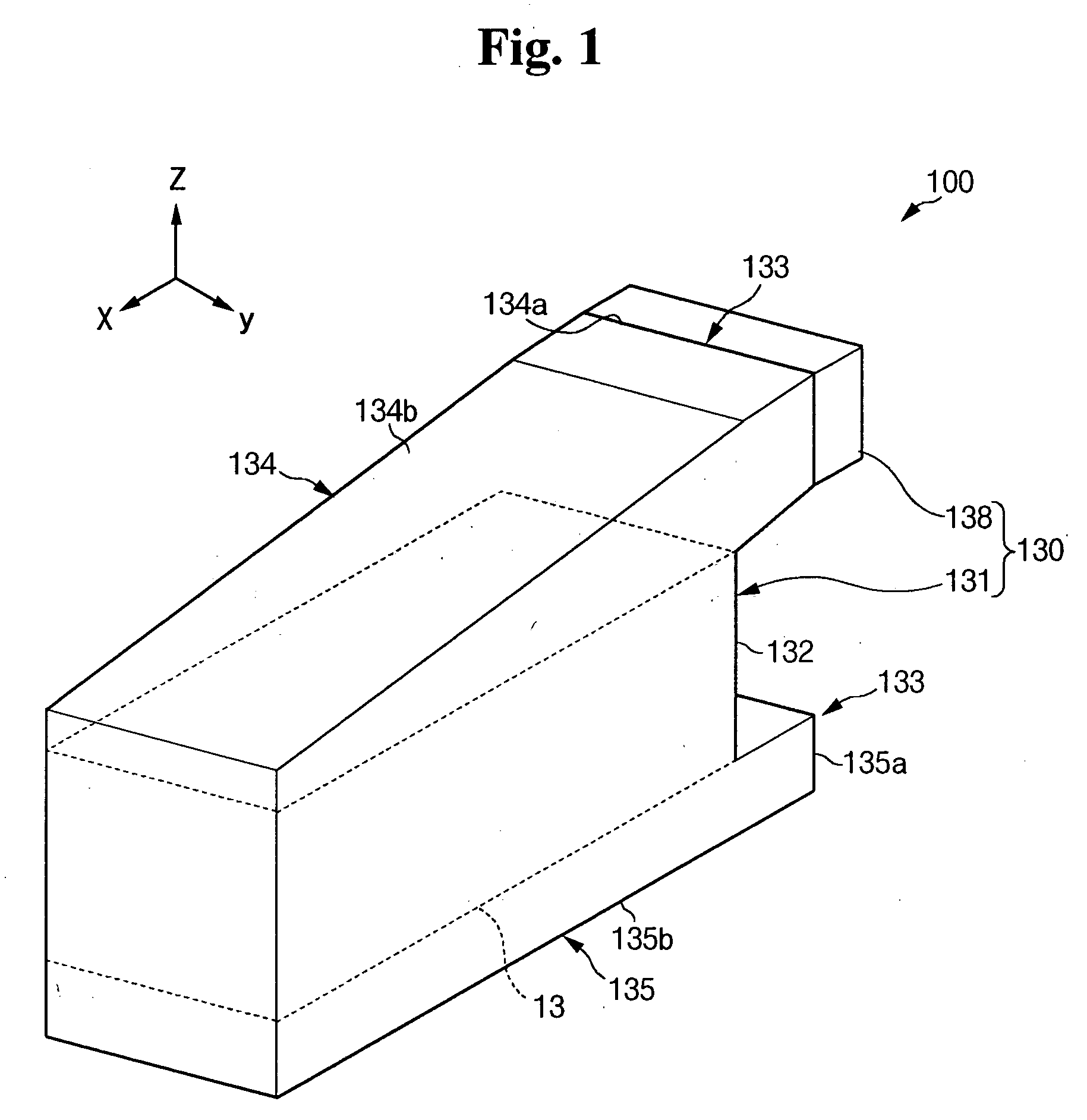
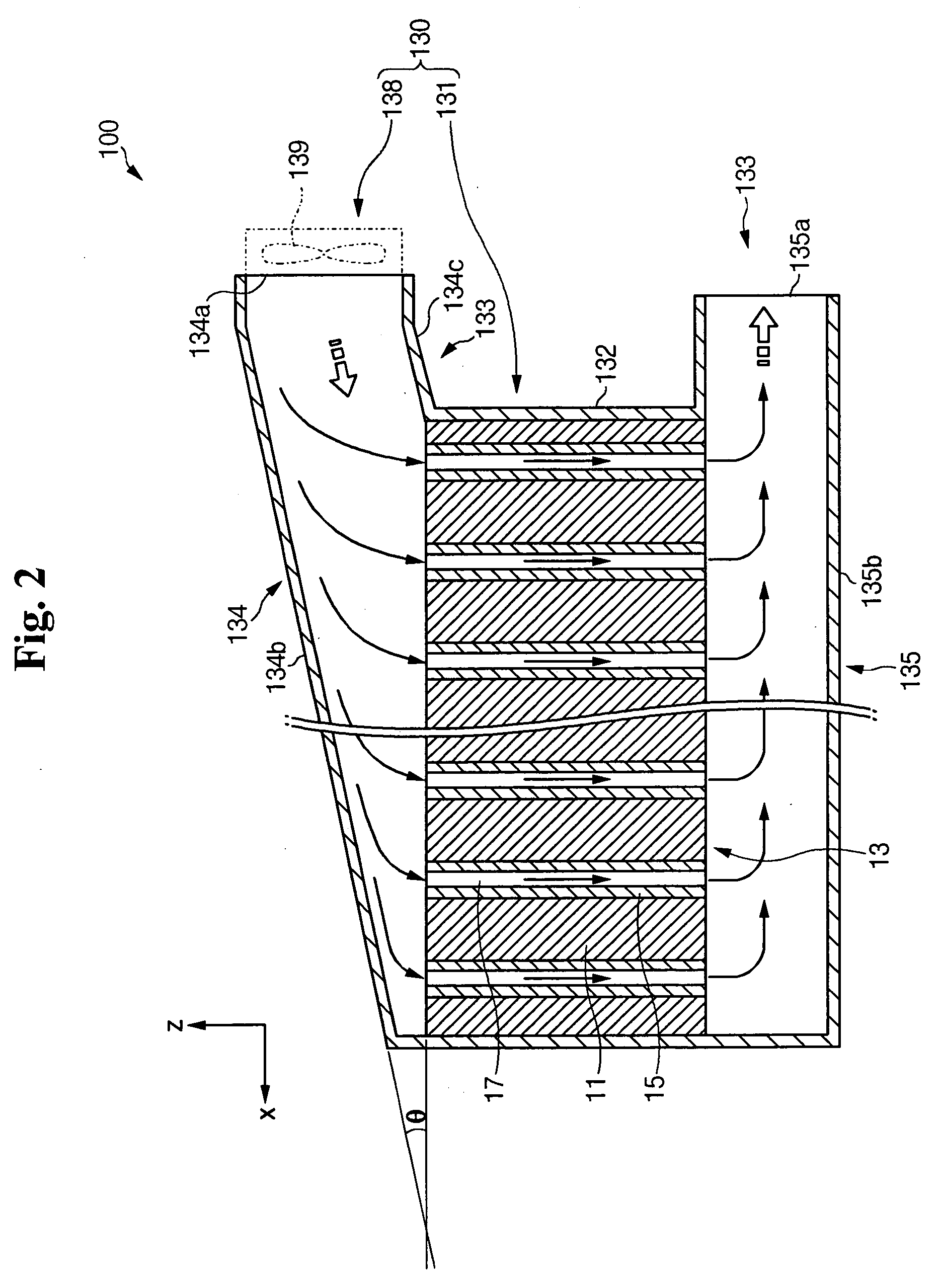
[0042] As shown in FIGS. 1 and 2, the battery module 100 according to the present embodiment is a high-capacity battery module, and includes a plurality of unit cells 11 serially arranged and spaced from each other.

[0043] In this embodiment, each unit cell has a secondary battery having an electrode assembly including positive and negative electrode plates interposed with a separator to charge and discharge electric power.

[0044] A cell barrier 15 is provided between the neighboring unit cells 11 as well as between the outermost unit cell 11 and the wall of the housing 131 to maintain the distance between the unit cells 11 and to support the sidewall of each unit cell 11. An air ventilation channel 17 is formed at the respective cell barriers 15 to ventilate a cooling air with a relatively low temperature through the unit cells 11.

[0045] As shown in FIG. 3, the air ventilation channels 17 may be formed with at least one breakthrough hole spanning from edge 17a to edge 17b of the c...


PUM

PropertyMeasurementUnit
inclination angleaaaaaaaaaa

Abstract

A battery module with a cooling system capable of ventilating a uniform amount of air through the respective unit cells. The battery module includes a plurality of unit cells spaced from each other and a housing for accommodating the unit cells therein. The housing has an inflow guide side inclined with respect to the direction perpendicular to the interfacial surfaces of the plurality of unit cells, an air inlet for introducing a temperature controlling air, and an air outlet for discharging the air ventilated through the unit cells.

Description

CROSS-REFERENCE TO RELATED APPLICATION [0001] This application claims priority to and the benefit of Korean Patent Application Nos. 10-2004-0086604, 10-2004-0086605, and 10-2004-0086642 filed with the Korean Intellectual Property Office on Oct. 28, 2004, the entire content of which is incorporated herein by reference. BACKGROUND OF THE INVENTION [0002] 1. Field of the Invention [0003] The present invention relates to a secondary battery, and in particular, to a secondary battery module having a cooling system for cooling the secondary battery module. [0004] 2. Description of Related Art [0005] Generally, secondary batteries are based on a rechargeable mechanism which is distinguished from that of primary cells where only the irreversible conversion of chemical to electrical energy is made. Secondary batteries may be classified into low-capacity batteries and high-capacity batteries. Low-capacity batteries are used as the power supply for small portable electronic devices, such as ce...

Claims


Application Information

Patent Timeline
Patent Type & Authority Applications(United States)
IPC IPC(8): H01M10/50H01M2/12H01M10/60H01M10/613H01M10/625H01M10/647H01M10/651H01M10/652H01M10/6551H01M10/6555H01M10/6557H01M10/6561H01M10/6563H01M10/6566H01M10/663H01M50/209H01M50/289
CPCH01M2/1072H01M10/5004H01M10/5008H01M10/5016H01M10/5032H01M10/5038H01M10/5057H01M10/5059H01M10/5067H01M10/5073H01M10/625H01M10/6563H01M10/647H01M10/6556H01M10/652H01M10/6557H01M10/617H01M10/6566H01M10/613Y02E60/10H01M50/209H01M50/289
Inventor LEE, GUN-GOOJEON, YOON-CHEOLKIM, TAE-YONGCHEONG, KYEONG-BEOM
Owner SAMSUNG SDI CO LTD
Learn More