Natural gas injection system for regenerative thermal oxidizer

a technology of regenerative thermal oxidizer and injection system, which is applied in the direction of combustion control, combustion types, furnaces, etc., can solve the problems that natural gas is also subject to price fluctuation, and achieve the effect of reducing the firing rate and saving energy in the combustion chamber

Active Publication Date: 2006-05-04
ZENVIRO TECH HLDG INC
View PDF49 Cites 11 Cited by
  • Summary
  • Abstract
  • Description
  • Claims
  • Application Information

AI Technical Summary

Benefits of technology

[0008] The natural gas is directly injected and mixes into polluted waste gas streams monitored by the system as it passes up through the center section toward the upper heat exchanger section. The natural gas and most of the polluted air combust in the upper heat exchanger section, prior to reaching the combustion chamber. The result is a savings in energy in the combustion chamber by reducing the natural gas and combustion air required to maintain a setpoint temperature. Furthermore, the Nitrous Oxide (NOx) generated by the main burner can be eliminated or greatly reduced

Problems solved by technology

Natural gas, however, is also

Method used


Image

  • Natural gas injection system for regenerative thermal oxidizer
  • Natural gas injection system for regenerative thermal oxidizer
  • Natural gas injection system for regenerative thermal oxidizer

Examples


Embodiment Construction

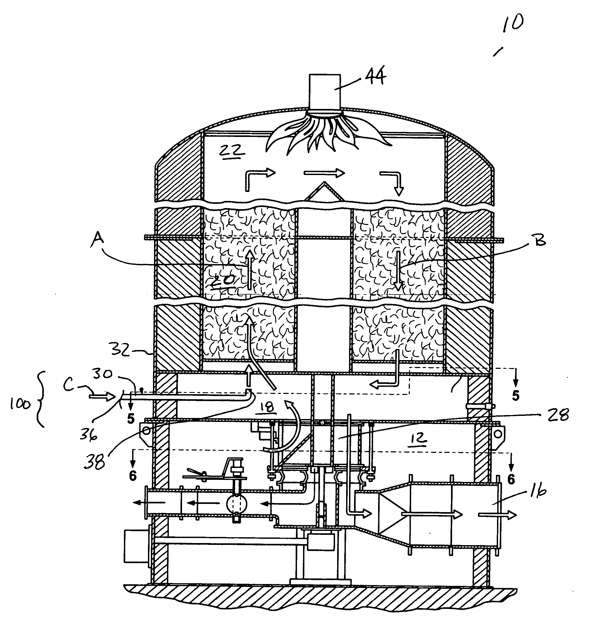
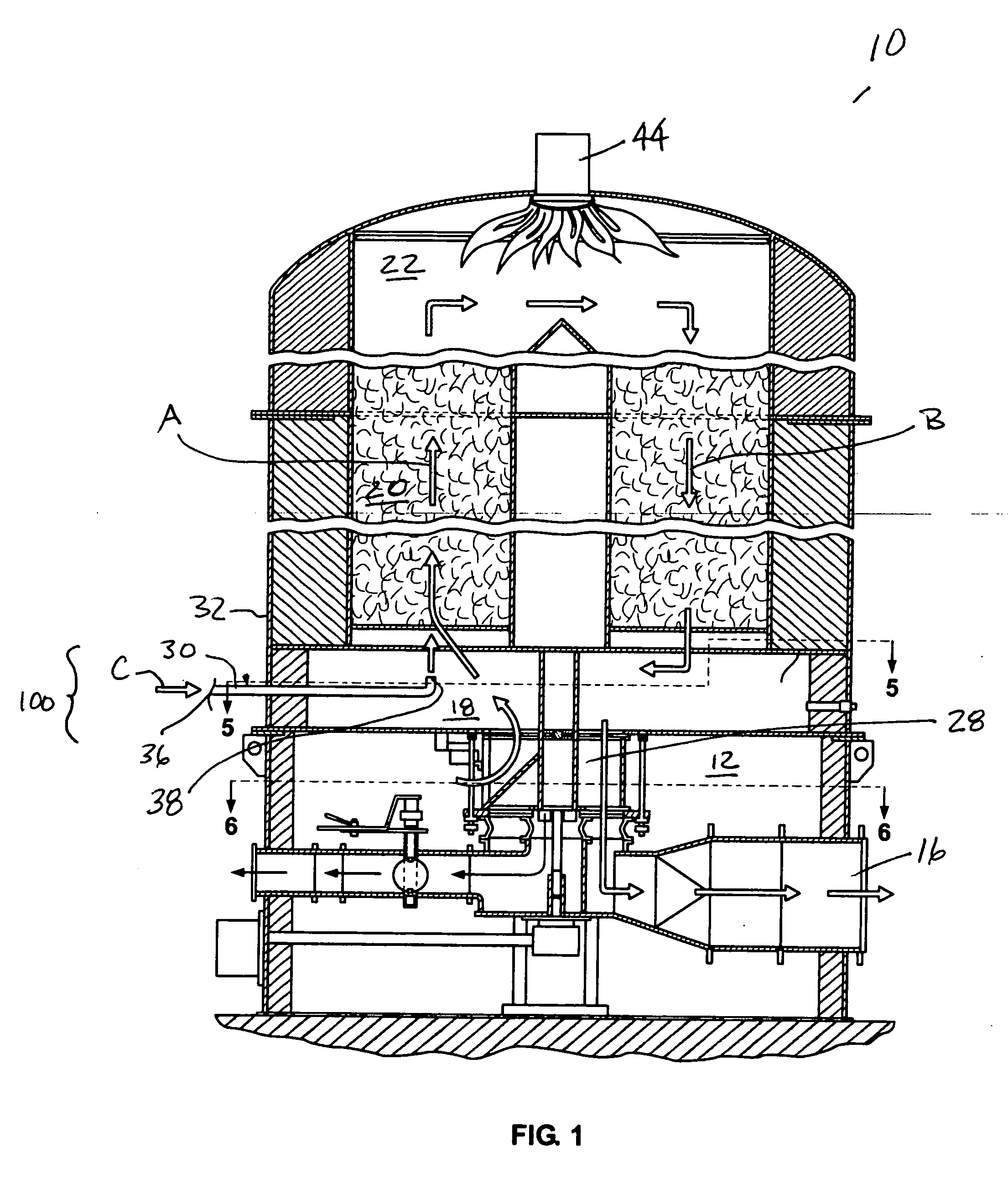
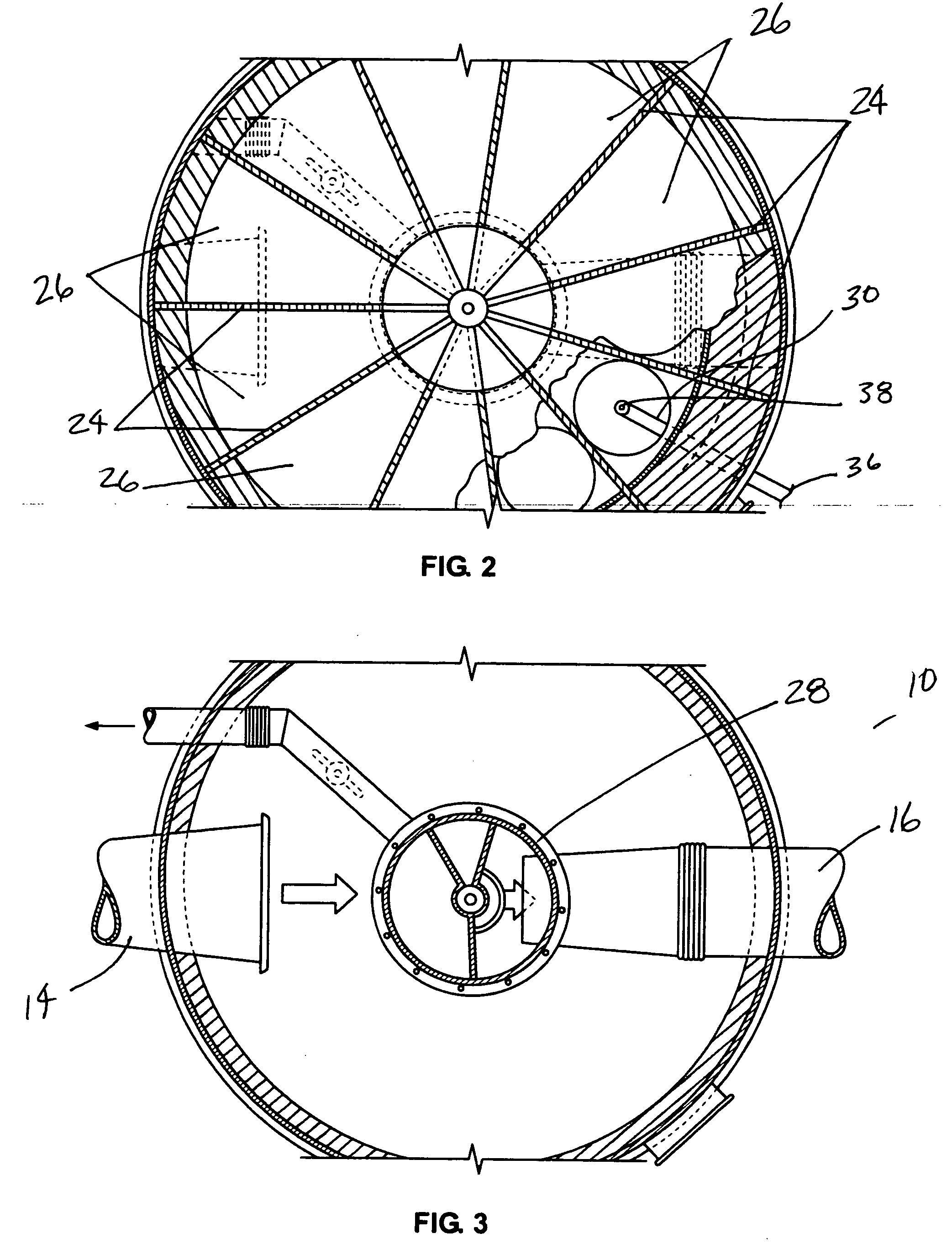
[0018] The following examples further illustrate the invention but, of course, should not be construed as in any way limiting its scope. Referring to the drawings, FIGS. 1-3 illustrate a regenerative thermal oxidizer (“RTO”) 10, a general description of which can be found in U.S. Pat. No. 5,562,442, incorporated herein by reference. Referring to FIG. 1 the RTO 10 generally includes a lower section 12 containing an inlet 14, as shown in FIG. 3, and an outlet 16. A center section 18 is located above the lower section 12 and a bed of heat exchanger material 20 is positioned vertically above the center section 18. An upper combustion chamber 22 is located above the heat exchanger bed 20. Turning to FIG. 2, the center section 18 includes a plurality of centrally intersecting walls 24 that divide the center section 18 into a plurality of wedge-shaped chamber segments 26.

[0019] As will be understood to those of ordinary skill in the art, the RTO 10 also includes a rotary distributor 28 th...


PUM


Abstract

The present invention provides a system and method for injecting natural gas in an RTO. The RTO may be, for example, a known type that has a rotary distributor, a center section divided into pie-shaped segments above the rotary distributor, a heat exchanger section above the center section, and a combustion chamber above the heat exchanger. According to an aspect of the invention, the system introduces gas into segments of the center section in a sequenced manner via cycling on/off control valves. In a particular embodiment, the natural gas is injected at a specific location of a respective segment within the center section that is past the rotary distributor seals and directly under the bottom of the heat exchanger bed. According to the injection sequence, the injection of natural gas into the segment commences when the segment begins to receive inlet waste gas streams, and injection ceases before the flow through the sector changes or stops. In an embodiment, each injection cycle may last a predetermined time to preferably achieve a constant flow of natural gas in the intake stream of process air as the rotary distributor delivers such flow sequentially among the segments.

Description

CROSS-REFERENCE TO RELATED APPLICATIONS [0001] This patent application claims the benefit of U.S. Provisional Patent Application No. 60 / 623,202, filed Oct. 29, 2004.FIELD OF THE INVENTION [0002] This invention generally relates to regenerative thermal oxidizers (RTOs) and more particularly relates to a natural gas injection system for an RTO. BACKGROUND OF THE INVENTION [0003] A regenerative thermal oxidizer is used to clean polluted waste gas from an industrial process. Conventional RTOs are disclosed, for example in U.S. Pat. Nos. 5,562,442 and 5,700,443, which are incorporated herein by reference. [0004] An RTO is constructed to receive polluted waste gases from an industrial process, cleanse the gas, and permit cleansed gas to exit the RTO to the environment. The RTO includes a lower section having an inlet to receive incoming waste gas that is polluted or contaminated, and a centrally positioned rotary distributor in the lower section that is used in controlling gas flow via a ...

Claims


Application Information

Patent Timeline
IPC IPC(8): F23G7/08
CPCF23C99/006F23G7/068F23N2025/04F23N2035/18F23N2037/02F23N2225/04F23N2235/18F23N2237/02
Inventor BAKER, ROBIN J.GINGER, BRADLEY L.
Owner ZENVIRO TECH HLDG INC
Why Eureka
Try Eureka