Dental filing tool

a filing tool and dental technology, applied in the field of dental filing tools, can solve the problems of inconvenient use, inconvenient use, inconvenient use, etc., and achieve the effects of convenient holding and maneuvering, efficient and effective filing and grinding, and sufficient tension

Active Publication Date: 2006-05-04
DIRECTA
View PDF12 Cites 6 Cited by
  • Summary
  • Abstract
  • Description
  • Claims
  • Application Information

AI Technical Summary

Benefits of technology

[0006] The main object of the present invention is to provide a filing tool which secures a filing strip with sufficient tension, that is easy to hold and maneuver while inserted in a patient's mouth to efficiently and effectively file and grind between teeth and the crown, bridge, onlay, or inlay for an accurate fitting.
[0007] Another object of the present invention is to provide a filing tool that inflicts the least amount of discomfort and injury to patient's gums and lips during filing.
[0008] Accordingly, the present invention is comprised of a handle made of a formable material, not limited to but like plastic, which has a horizontal arm element with a first vertical arm extending downward from its first end and a second vertical arm extending from its second end forming an arch. Between the first and second vertical arms a filing strip is secured at each end tautly with tension. The horizontal arm which arches above and flush with the filing strip from its top edge tapers downwards towards the filing strip reducing in thickness to a fine beveled edge. The horizontal arm which arches above and flush with the filing strip has a middle portion with a reinforcing raised flat segment on both sides of the horizontal arm that increases thickness to achieve rigidity. Additionally, the first and second vertical arms of the handle also taper in thickness from the outside edge inwards towards the filing strip reducing in thickness to a fine beveled edge. The outside wider edges of the first and second vertical arms have a flattened surface area on which opposable fingers may be placed to hold the invention to facilitate an easy sawing back and forth movement to file.

Problems solved by technology

This method is tedious, inefficient, and inexact.
It is a time consuming process and there is possibility of over-grinding, in which case a whole other replacement restoration must be reconstructed which involves an expensive lab fee for the practitioner and wasted time for the patient and the practitioner, not to mention it is inconvenient for the patient who suffers for the delay and pain.
Unfortunately holding the filing strip in such as manner is cumbersome in the patient's mouth and impedes the practitioner from achieving desired angles and restricts range of motion to effectively file.
Especially when the patient is receiving crowns, bridges, onlays, or inlays in the back of the mouth where it is considerably more difficult to access, it is difficult for the practitioner to file since both hands are needed to hold tension in the strip and often a patient's mouth is too small and cannot open wide enough to accommodate comfortably.
This method is inefficient, tiresome for the practitioner, and uncomfortable for the patient.
Moreover, because of the difficulty involved handling the filing strip, often patients sustain suffer small cuts due to the sharp edges of the strip coming in contact with gums and lips while filing the tooth or restoration.
This bow and handle are too long to maneuver in the mouth and limit the optimal length of the abrasive strip.
The strip itself is the important working surface in interproximal filing and the short length of the strip in this method is ineffective because the strip itself is too short to effectuate a sawing motion to file away material, particularly for posterior teeth.
Also in this method, it is a hassle to replace the filing strip after each use.

Method used


Image

  • Dental filing tool
  • Dental filing tool
  • Dental filing tool

Examples


Embodiment Construction

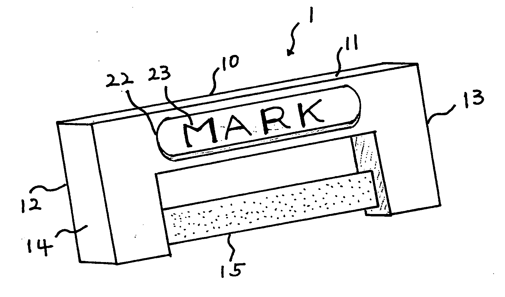
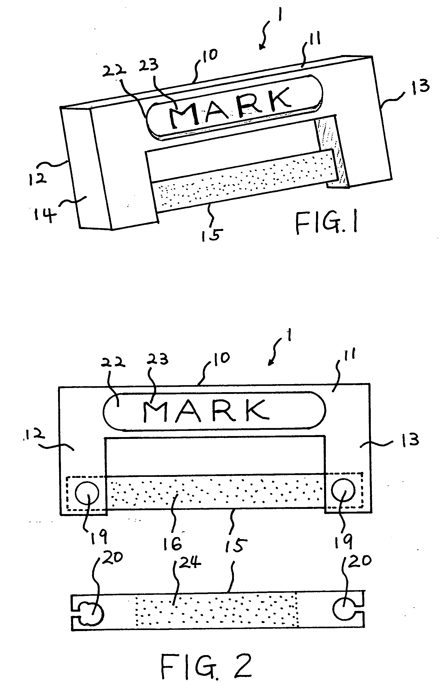
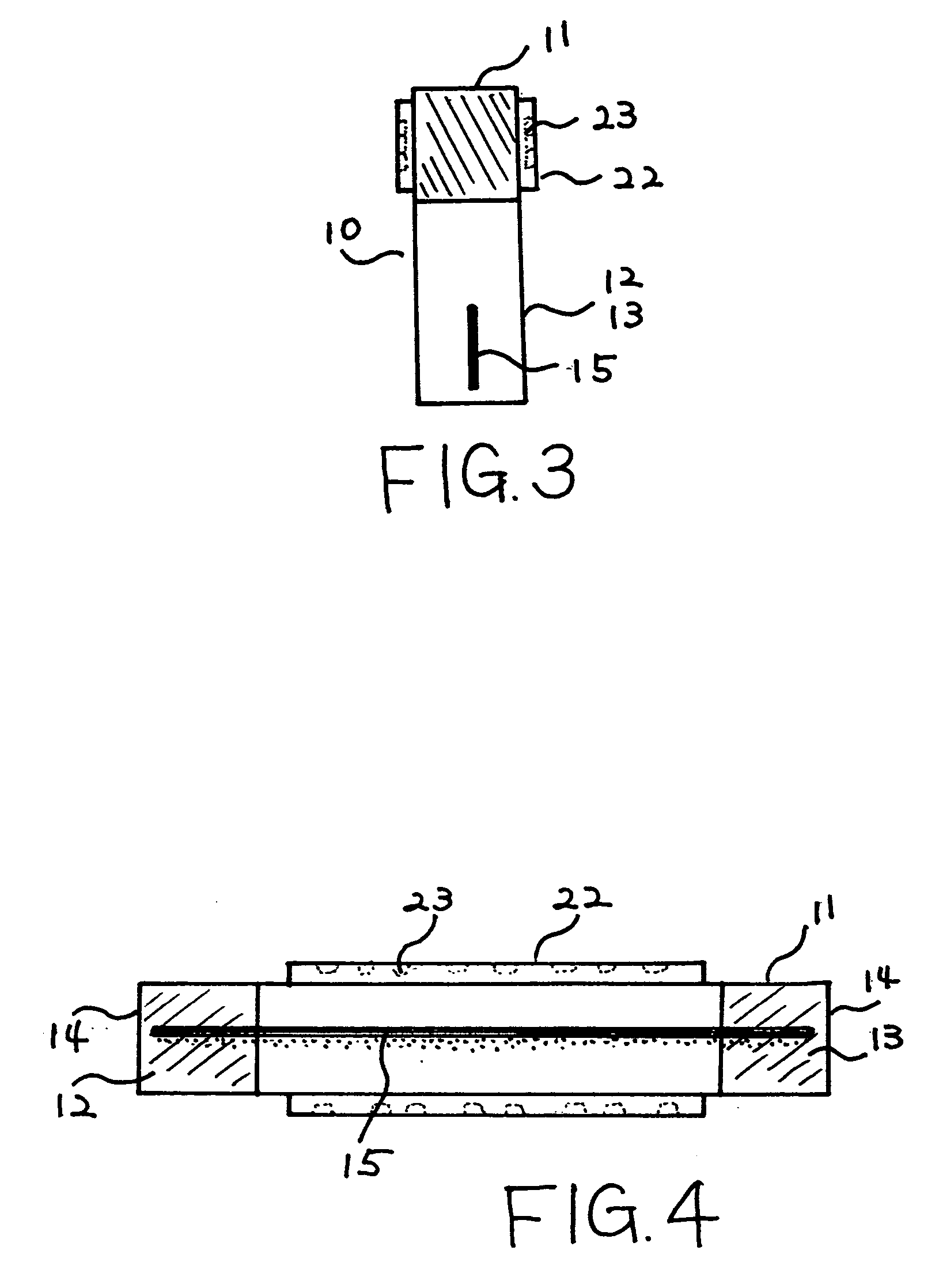
[0017] The dental filing tool 1 shown as preferred embodiment in FIGS. 1 and 2, comprises of handle component 10 made of a formable material, not limited to but like plastic, which has a horizontal arm element 11 with a first vertical arm 12 extending downward from its first end and a second vertical arm 13 extending from its second end forming an arched structure. Between the first 12 and second vertical arms 13 is a filing strip 15 secured at each of its ends tautly with tension.

[0018] The one or both lateral sides of the filing strip 15 are coated with some superfine abrasive material 16, especially but not limited to diamond dust. The filing strip 15 is coated with abrasive material on its entire or partial surface 16 and 24. The filing strip 15 utilized in the dental filing tool 1 is of the appropriate thickness to be inserted into the interproximal area between teeth and / or crowns, bridges, onlays, or inlays, generally referred to as restorations.

[0019] The outside edges of ...


PUM


Abstract

A dental filing tool having a handle easy to hold between fingers which arches over and secures at both ends of a thin filing strip coated with some superfine abrasive material, especially but not limited to diamond dust, or alternatively a sharp cutting system along the edge or lateral surface. From hole-like openings with slots at each end, the strip is fastened between each end of the handle with sufficient tension in the strip to create a rigid filing and grinding surface. The handle is made from formable materials not limited but like plastics injected into mold with which a filing strip is inserted. On the outside edge of each vertical arm of the handle is a smooth flatten surface where to place fingers to hold the handle. The dental filing tool is disposable when the abrasive material of the filing strip wears off.

Description

BACKGROUND OF THE INVENTION [0001] This invention relates to dental filing tool, more particularly to a dental filing tool that holds a thin filing strip coated with superfine abrasive material or has a sharp cutting edge for efficient filing of the interproximal area and fitting of dental crowns, bridges, onlays, inlays and fillings. [0002] The current conventional method for fitting dental crowns, bridges, onlays and inlays, herein referred to generally as restorations, involves the dental practitioner sliding colored carbon paper, the thickness of which is the recommended measured distance between teeth, in between the interproximal area of the tooth and the restoration. The carbon paper marks with carbon ink the proximal contact area where the two surfaces of the teeth and / or restoration are too close, and then the practitioner grinds the restoration with a rotary instrument to remove excess material. This method is tedious, inefficient, and inexact. The dental practitioner has ...

Claims


Application Information

Patent Timeline
Patent Type & Authority Applications(United States)
IPC IPC(8): A61C3/06
CPCA61C3/06A61C3/12
Inventor KIM, DANIEL SUNG-YUL
Owner DIRECTA
Why Eureka
Try Eureka