
Monitoring apparatus of arterial pulses and method for the same

a monitoring apparatus and pulse technology, applied in the field of monitoring apparatus of arterial pulses and method for the same, can solve the problems of patient discomfort in long-term operation, signal baseline drift, signal-to-noise ratio degradation, etc., and achieve the effect of effective us

Inactive Publication Date: 2006-05-04
MARCOTT INT INVESTMENT
View PDF10 Cites 31 Cited by
  • Summary
  • Abstract
  • Description
  • Claims
  • Application Information

AI Technical Summary

Benefits of technology

"The present invention provides a monitoring apparatus for arterial pulses using a non-contact measurement scheme. The apparatus includes an antenna board, an analog board, a digital board, and a display device. The method involves radiating ultra wideband electromagnetic waves to an arterial blood vessel and measuring the time variation of phase differences between the scattered waves and the radiated waves. The movement of the arterial vessel is detected based on the phase difference. The technical effects include improved accuracy and non-invasive monitoring of arterial pulses."

Problems solved by technology

However, it may cause the patient's discomfort in long-term operation due to prolong compression of the skin tissue.
Furthermore, skin irritation and sweating may be induced, which results in signal-to-noise ratio degradation and signal baseline drift.
Although the sensor does not require close contact with the skin, it can only be used effectively on peripheral extremities where enough light passing through vascular bed can be received by the light detector.
The device is designed for remote operation and thus cannot be attached to the patient under examination.
Therefore, it is not suitable for portable long-term monitoring purpose.

Method used


Image

  • Monitoring apparatus of arterial pulses and method for the same
  • Monitoring apparatus of arterial pulses and method for the same
  • Monitoring apparatus of arterial pulses and method for the same

Examples


Embodiment Construction

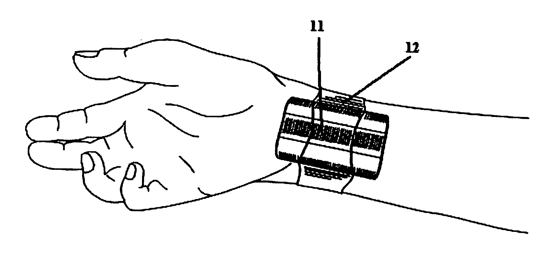
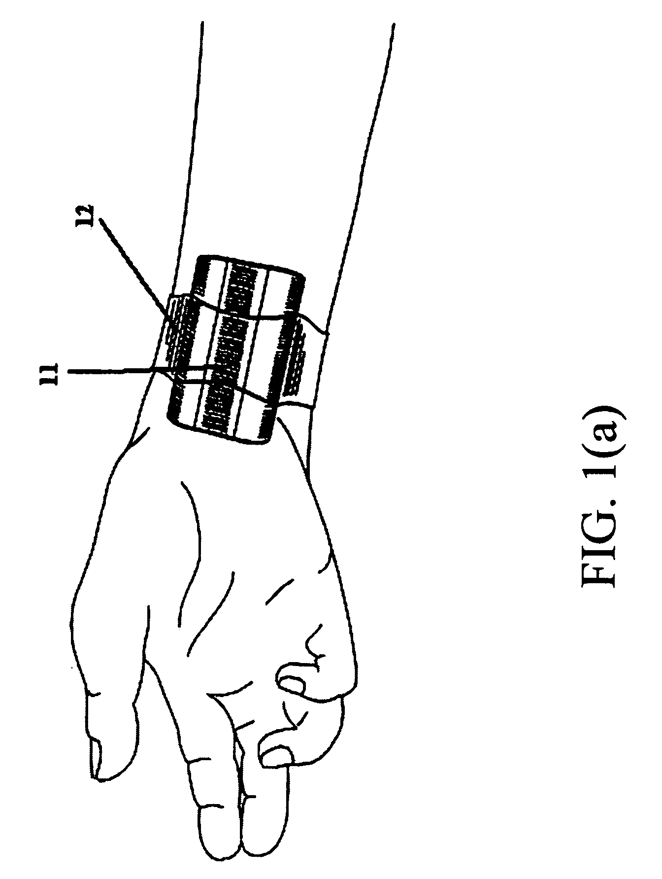
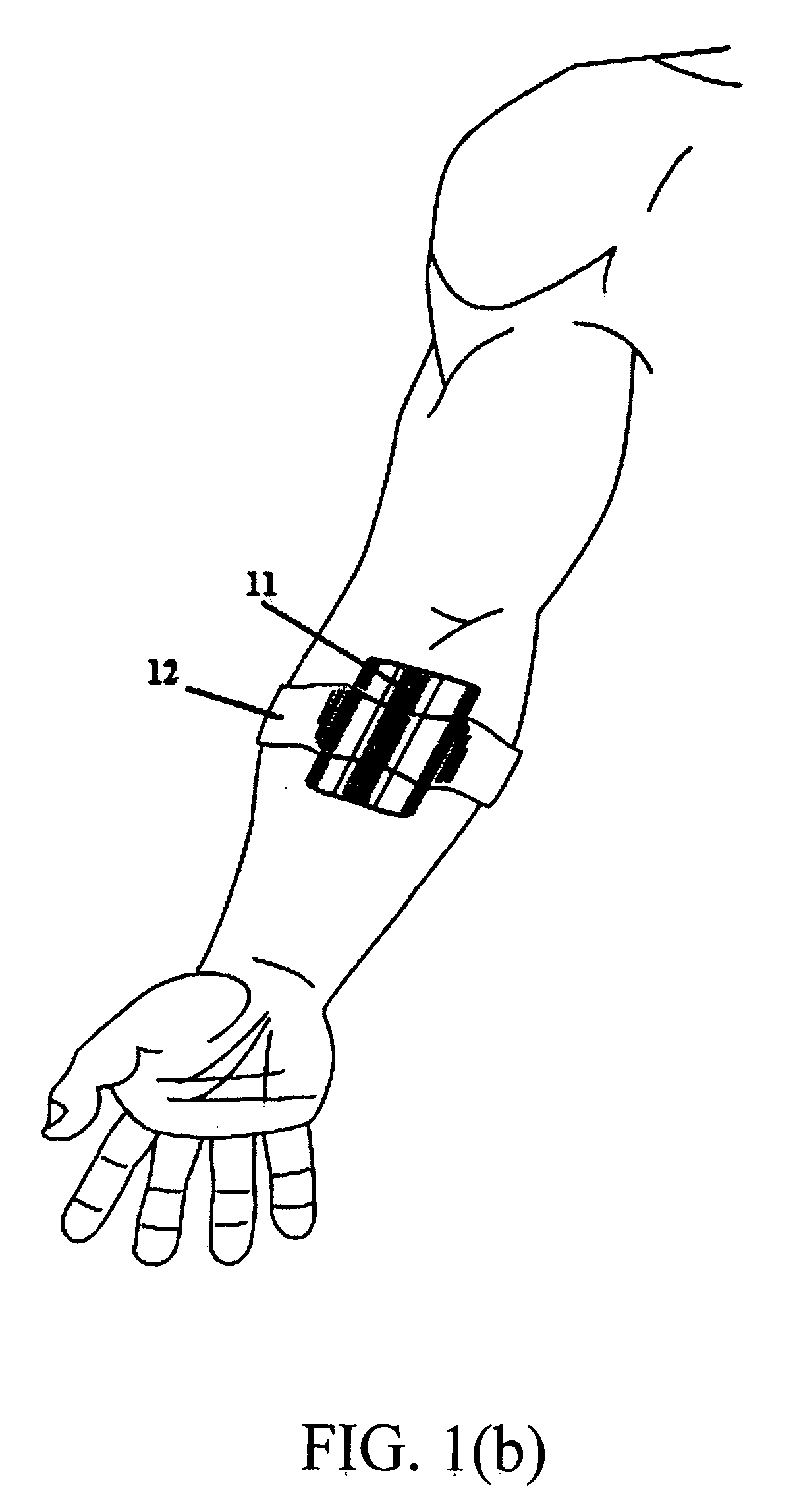
[0031] FIGS. 1(a), 1(b) and 1(c) show the present monitoring apparatus 10 attached onto human body sites where movements of arterial blood vessels can be detected. The strap 12 is used for attaching the monitoring apparatus 10 onto body sites without exerting pressure on the skin of the user.

[0032] FIGS. 2(a) and 2(b) show the monitoring apparatus 10 according to the present invention. As shown in FIG. 2(a), the monitoring apparatus 10 comprises an antenna board 23, an analog board 24 and a digital board 25. As shown in FIG. 2(b), the antenna board 23 comprises a transmission antenna 21 and a reception antenna 22 from which a series of probing pulses are emitted and received through a membrane 20. The transmission antenna 21 and the reception antenna 22 are both in the form of bow-tie antenna. Due to the nature of the non-contact measurement scheme, the membrane 20 does not serve the purpose of signal energy conversion but acts as a part of the enclosure for the monitoring apparatu...


PUM


Abstract

A monitoring apparatus includes an antenna board including a transmission antenna for transmitting an ultra wideband electromagnetic wave to an arterial blood vessel and a reception antenna for receiving the ultra wideband electromagnetic wave scattered by the arterial blood vessel, an analog board with a plurality of electronic devices for acquiring analog signals representing the arterial pluses of the arterial blood vessel, a digital board with a plurality of electronic devices for digitalizing the analog signal, and a display device for showing the arterial pulses. The method for acquiring arterial pulses first radiates an ultra wideband electromagnetic wave to an arterial blood vessel, and measures the phase difference between the ultra wideband electromagnetic wave scattered by the arterial blood vessel and the reference ultra wideband electromagnetic wave. Finally, the arterial pulses are acquired based on the variation of the phase difference.

Description

RELATED U.S. APPLICATIONS [0001] Not applicable. STATEMENT REGARDING FEDERALLY SPONSORED RESEARCH OR DEVELOPMENT [0002] Not applicable. REFERENCE TO MICROFICHE APPENDIX [0003] Not applicable. FIELD OF THE INVENTION [0004] The present invention relates to a monitoring apparatus of arterial pulses and method for the same, and more particularly to a monitoring apparatus of arterial pulses using a non-contact measurement scheme in which an ultra wideband (UWB) electromagnetic wave is employed to detect the movement of an arterial blood vessel and method for acquiring arterial pulses using for the same. BACKGROUND OF THE INVENTION [0005] The purpose of monitoring arterial pulses is to alert patient or his / her caregivers of abnormal conditions of arterial circulatory system, which may lead to heart failure. Conventional technologies for monitoring patient's arterial pulses most commonly employ piezoelectric pressure sensors to obtain signal on body sites where arterial blood vessels are l...

Claims


Application Information

Patent Timeline
Patent Type & Authority Applications(United States)
IPC IPC(8): A61B5/00
CPCA61B5/02438
Inventor IMMOREEV, IGOR YAKOVLEVICHSAMKOV, SERGEY VITAL'EVICHTAO, TEH-HO
Owner MARCOTT INT INVESTMENT
Learn More