Intramedullary nail and associated method

Inactive Publication Date: 2006-05-04
BIOMET CV
View PDF42 Cites 90 Cited by
  • Summary
  • Abstract
  • Description
  • Claims
  • Application Information

AI Technical Summary

Benefits of technology

[0028] Another technical advantage of the present invention includes the ability to obtain two locked portions within the same slot on an intramedullary nail. For example, according to one aspect of the present invention, an intramedullary nail is provided with a slot having spaced apart threaded portions. A fastener may be positioned in either one of the first and second threaded portions of the intramedullary nail. Thus, the present invention provides for two locked portions within the same slot of an intramedullary nail.
[0029] The technical advantages of the present invention further include the ability to obtain a dynamic configuration in an intramedullary nail with limited motion. For example, according to one aspect of the present invention, an intramedullary nail is provided with a slot with a large round portion filled with a resorbable material. The fastener is positioned in the resorbable material and is permitted to move over time as the resorbable material resorbs within the round portion of the slot. The round portion of the slot limits the motion during the dynamization. Thus, the present invention provides for the intramedullary nail, which provides for dynamization with a limited linear motion.
[0030] The technical advantages of the present invention further include the ability to obtain dynamization with extended motion. For example, according to another aspect of the present invention, an intramedullary nail is provided with a slot having a small screw, which may move substantially longitudinally along the slot. The slot may be filled completely with resorbable material, which resorbs over time, permitting the motion of the screw along the slot of the nail. Thus, the present invention provide

Problems solved by technology

These long bones are particularly exposed to trauma from accidents and as such often are fractured during such trauma and may be subject to complex devastating fractures.
Automobile accidents, for instance, are a common cause of trauma to long bones.
In particular, the femur and the tibia frequently fracture when the area around t

Method used


Image

  • Intramedullary nail and associated method
  • Intramedullary nail and associated method
  • Intramedullary nail and associated method

Examples


Embodiment Construction

[0087] Embodiments of the present invention and the advantages thereof are best understood by referring to the following descriptions and drawings, wherein like numerals are used for like and corresponding parts of the drawings.

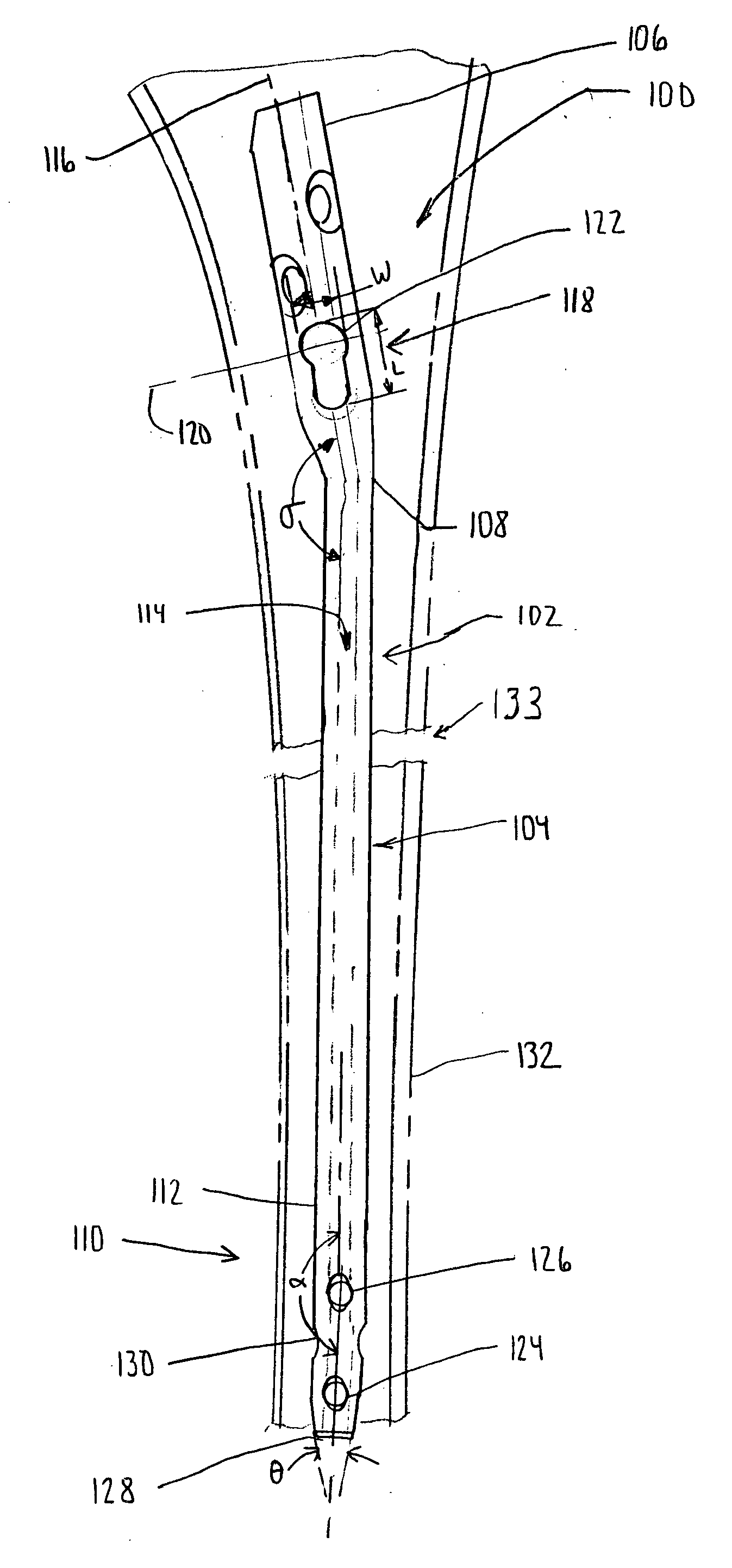
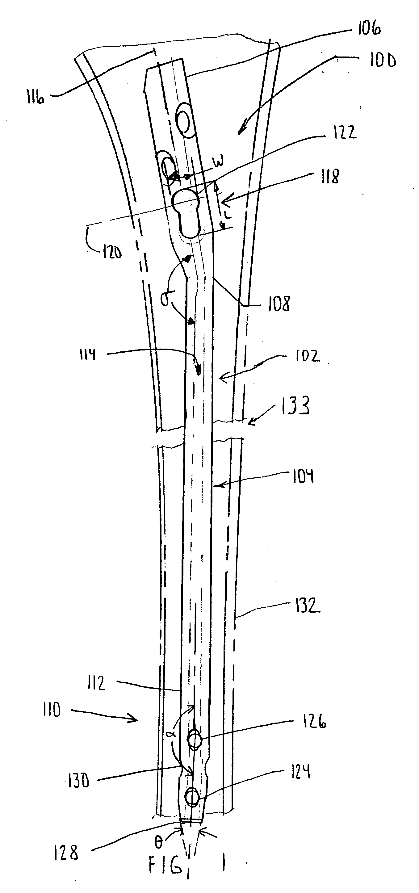
[0088] According to the present invention and referring now to FIG. 1, an intramedullary rod or nail 100 is shown for use in orthopaedic surgery. The nail 100 includes a body 102. The body 102 is elongated and may, for example, have a generally uniform cross-section and extend uniformly along its length. Alternatively, and as shown in FIG. 1, the body 102 may have a nonlinear shape to conform to the nonlinear shape of a long bone. For example as shown in FIG. 1, the body 102 includes a central portion 104 and a proximal portion 106 extending outwardly from first end 108 of the central portion 104. A distal portion 110 may extend outwardly from second end 112 of the central portion 104.

[0089] The body 102 may have any suitable shape and may, for simplicity, ...


PUM


Abstract

An intramedullary nail for use with a first fastener and a second fastener for use in orthopaedic surgery is provided. The nail includes a body defining a longitudinal axis of the body. The body defines an aperture through the body. The aperture has a first portion for cooperation with the first fastener to provide dynamic fixation and a second portion for cooperation with the fastener nail to provide static fixation.

Description

TECHNICAL FIELD OF THE INVENTION [0001] The present invention relates generally to the field of orthopaedics, and more particularly, to an intramedullary nail for use in trauma surgery. BACKGROUND OF THE INVENTION [0002] The skeletal system includes many long bones that extend from the human torso. These long bones include the femur, fibula, tibia, humerus, radius and ulna. These long bones are particularly exposed to trauma from accidents and as such often are fractured during such trauma and may be subject to complex devastating fractures. [0003] Automobile accidents, for instance, are a common cause of trauma to long bones. In particular, the femur and the tibia frequently fracture when the area around the knee is subjected to frontal automobile accidents. [0004] Often the distal or proximal portions of a long bone, for example, the femur and the tibia are fractured and must be reattached. [0005] Mechanical devices, most commonly in the form of pins, plates, and screws are common...

Claims


Application Information

Patent Timeline
IPC IPC(8): A61B17/56A61B17/72A61B17/58
CPCA61B17/72A61B17/7225A61B17/7233
Inventor MUTCHLER, AUSTIN W.
Owner BIOMET CV
Why Eureka
Try Eureka